Heatable Personal Lubricant Dispensor

a lubricant dispenser and personal technology, applied in the field of dispensers, can solve problems such as negative affect on sexual experience, and achieve the effects of reducing the risk of pregnancy, reducing the spread of disease, and being convenient to wear

Active Publication Date: 2013-06-13
MADIGAN STEPHEN J
View PDF3 Cites 3 Cited by
  • Summary
  • Abstract
  • Description
  • Claims
  • Application Information

AI Technical Summary

Benefits of technology

[0027]The present invention encourages the use of condoms in sexual activities thereby reducing the spread of disease, including the human immunodeficiency virus (HIV), which may result in AIDS, and reducing the risk of pregnancy. In one embodiment, the present invention discloses a disposable container comprising a condom compartment enclosing one or more condoms immersed in a liquid material such as personal lubricant, removably adjoined to at least one personal lubricant compartment enclosing a liquid material such as personal lubricant, and a kit comprising at least one condom compartment and at least one associated personal lubricant compartment. Prior to their removal, the contents of the condom compartment are heated by a device in which the compartment is seated. A condom substantially more lubricated than a typical packaged condom is easier to don. Also, the donning of a warm condom that has been a heated by a liquid material in which it is immersed is more sensually pleasing than donning a typical packaged condom. The portion of personal lubricant contained in the opened compartment, now warm, may be applied to the penis further facilitating the donning of the condom. The condom is preferably a male condom. Personal lubricants include a lubricant sold under the brand name KY, Durex, Astroglide, Liquid Silk, among others, and is not limited to water-based lubricants.

Problems solved by technology

The application of these lubricants at these temperatures may negatively affect the sexual experience.
Second, a raised annular ring positioned on the top wall of the condom compartment provides a barrier to the migration of liquid material out of the compartment and into the heating mechanism of a warming device in which the compartment is seated.

Method used


Image

  • Heatable Personal Lubricant Dispensor
  • Heatable Personal Lubricant Dispensor
  • Heatable Personal Lubricant Dispensor

Examples


first embodiment

[0071 of Combination Condom and Personal Lubricant Container—FIGS. 1, 2, 3, 4, 5, 6.

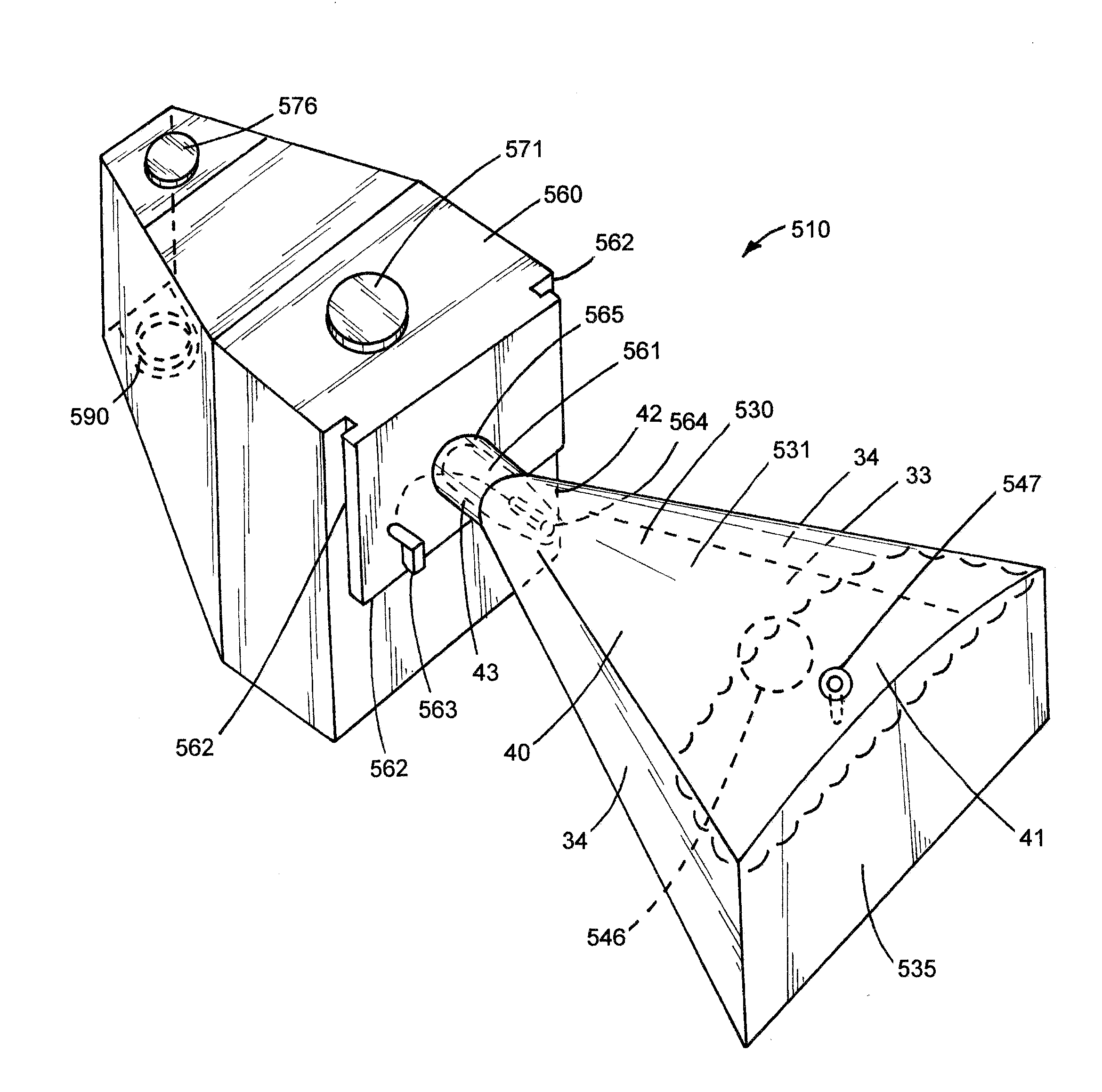
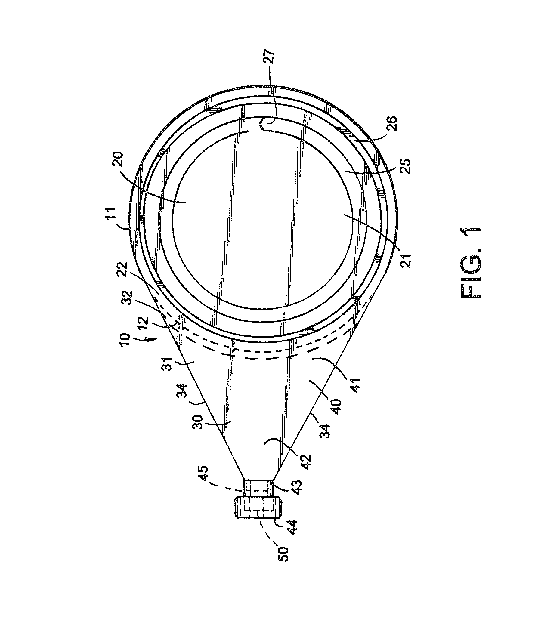
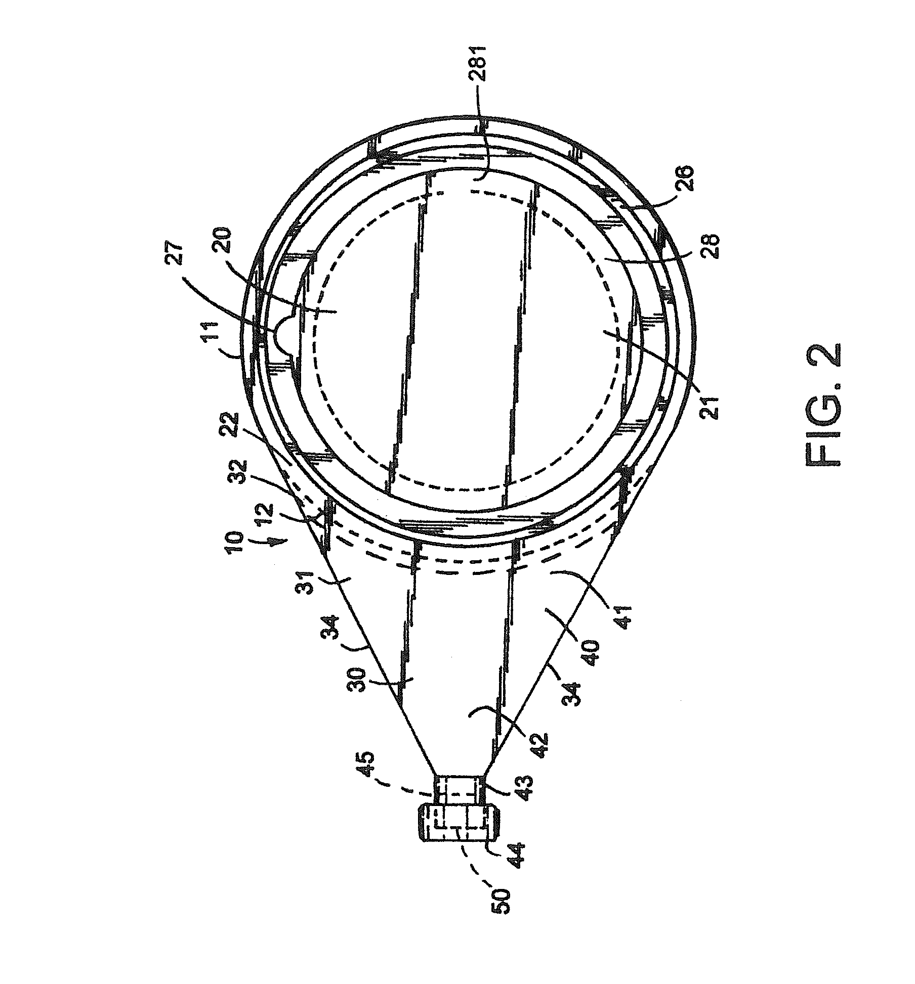
[0072]FIGS. 1-6 show various views of a first embodiment of article of manufacture comprising a condom compartment 20 removably adjoined to a personal lubricant compartment 30 hereinafter referred to as a combination condom and personal lubricant container 10. The container 10 is disposable. The compartments 20, 30 comprising the container 10 are constructed of a flexible, semi-rigid, or rigid packaging material 11 comprising properties that conduct heat, such as aluminum. The compartments are adjoined to one another at a protruding curved edge of the top wall of each compartment 22, 32 forming a common border. The compartments 20, 30 may be permanently separated from one another with the aid of perforations in the top of the container 12 arranged in a curved pattern along the common border.

[0073]FIGS. 1, 2 and 3 discussed below each show a top view of the first embodiment of the combination condom a...

second embodiment

[0085 of a Combination Condom and Personal Lubricant Container—FIGS. 7, 8, 9, 10.

[0086]FIGS. 7-10 show various views of an article of manufacture comprising a condom compartment 20 removably adjoined to congruent personal lubricant compartments 130, 150 hereafter referred to as a combination condom and personal lubricant container 110. The container 110 is disposable. The compartments 20, 130, 150 comprising the container 110 are constructed of a flexible, semi-rigid, or rigid packaging material 11 comprising properties that conduct heat such as aluminum. The condom compartment 20 positioned in the center of the container 110 is removably adjoined to congruent personal lubricant compartments 130, 150 flanking the condom compartment at a protruding curved edge of the top wall of each compartment 22, 132, 152 forming a common border. The congruent compartments 130, 150 may be detached from the condom compartment 20 with the aid of perforations in the top of the container 112 arranged ...

third embodiment

[0097 of a Combination Condom and Personal Lubricant Container—FIGS. 11, 12, 13, 14.

[0098]FIGS. 11-14 show various views of an article of manufacture comprising a condom compartment 220 removably adjoined to a personal lubricant compartments 230 hereinafter referred to as a combination condom and personal lubricant container 210. The container 210 is in the shape of a pentagon. The container 210 is disposable. The compartments 220, 230 comprising the container 210 are constructed of a flexible, semi-rigid, or rigid packaging material 11 comprising properties that conduct heat such as aluminum. The condom compartment 220 is removably adjoined to a personal lubricant compartment 230 at a protruding straight edge of the top wall of each compartment 222, 232 forming a common border. The compartments 220, 230 may be detached from one another with the aid of perforations in the top of the container 212 arranged in a straight pattern along the common border.

[0099]FIG. 11 shows a top view o...


PUM


Abstract

A personal lubricant dispenser includes an enclosure, a pre-delivery chamber, one or more heating elements proximate to the pre-delivery chamber, an electrical connector disposed on an exterior of the enclosure and electrically connected to the heating elements, an inlet cavity disposed above the pre-delivery chamber, a piercing element attached to the inlet cavity, a inlet valve (normally closed) connecting the inlet cavity to the pre-delivery chamber, a inlet actuator disposed on the exterior of the enclosure and operably connected to the inlet valve to open the inlet valve, an outlet cavity disposed below the pre-delivery chamber, an outlet valve (normally closed) connecting the outlet cavity to the pre-delivery chamber, an outlet actuator disposed on the exterior of the enclosure and operably connected to the outlet valve to open the outlet valve, and a spout disposed on or within the exterior of the enclosure and connected to the outlet cavity.

Description

PRIORITY CLAIM[0001]This patent application is a continuation-in-part application of U.S. patent application Ser. No. 13 / 289,890 filed on Nov. 4, 2011, now U.S. Pat. No. 8,365,738, and entitled “Combination Condom and Personal Lubricant Container,” which is a divisional patent application of U.S. patent application Ser. No. 12 / 447,255 filed on Apr. 25, 2009, now U.S. Pat. No. 8,074,653, and entitled “Combination Condom and Personal Lubricant Container,” which is a Section 371 U.S. national phase application of PCT / US07 / 81946 filed on Oct. 19, 2007, which claims priority to U.S. provisional patent application Ser. Nos. 60 / 930,558 filed on May 17, 2007 and 60 / 854,281 filed on Oct. 25, 2006, all of which are hereby incorporated by reference in their entirety.[0002]The patent application is related to U.S. patent application Ser. No. 12 / 989,647, filed on Apr. 8, 2011 and entitled “Device for Heating Products Used in Sexual Activities,” which is hereby incorporated by reference in its en...

Claims


Application Information

Patent Timeline
Patent Type & Authority Applications(United States)
IPC IPC(8): B67D3/00
CPCA61F6/005B67D3/0022B05C5/001B05C11/1042B65D47/38B65D83/265B05B11/104B05B11/1032
Inventor MADIGAN, STEPHEN J.
Owner MADIGAN STEPHEN J
Why Eureka
Try Eureka