Integrated energy generating damper

a technology of energy generating dampers and dampers, which is applied in the direction of mechanical equipment, machines/engines, transportation and packaging, etc., can solve the problems of unidirectional flow through the hydraulic motor, spin, and dissipate a significant amount of hea

Active Publication Date: 2013-06-13
CLEARMOTION INC
View PDF18 Cites 73 Cited by
  • Summary
  • Abstract
  • Description
  • Claims
  • Application Information

AI Technical Summary

Benefits of technology

[0008]Aspects relate to an energy-generating device that captures energy associated with relative motion, whilst providing damping t

Problems solved by technology

Primary damper technologies have been in use for decades and can be split into two main groups: monotube dampers and twin-tube dampers (although certain tri-tube dampers have been produced, these are used for specialized adaptive dampers and are not in wi

Method used


Image

  • Integrated energy generating damper
  • Integrated energy generating damper
  • Integrated energy generating damper

Examples


Embodiment Construction

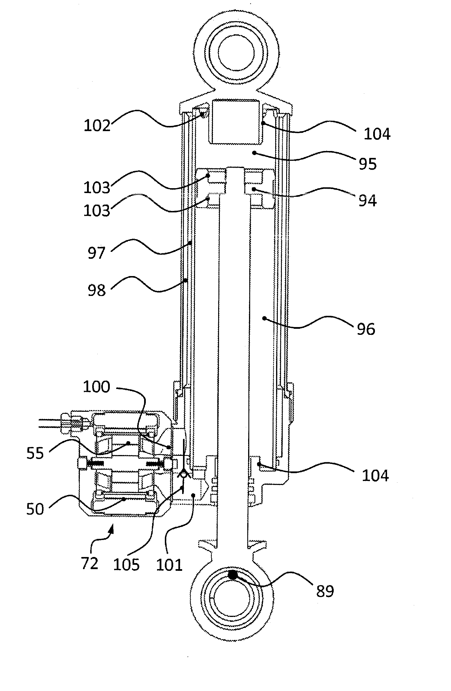
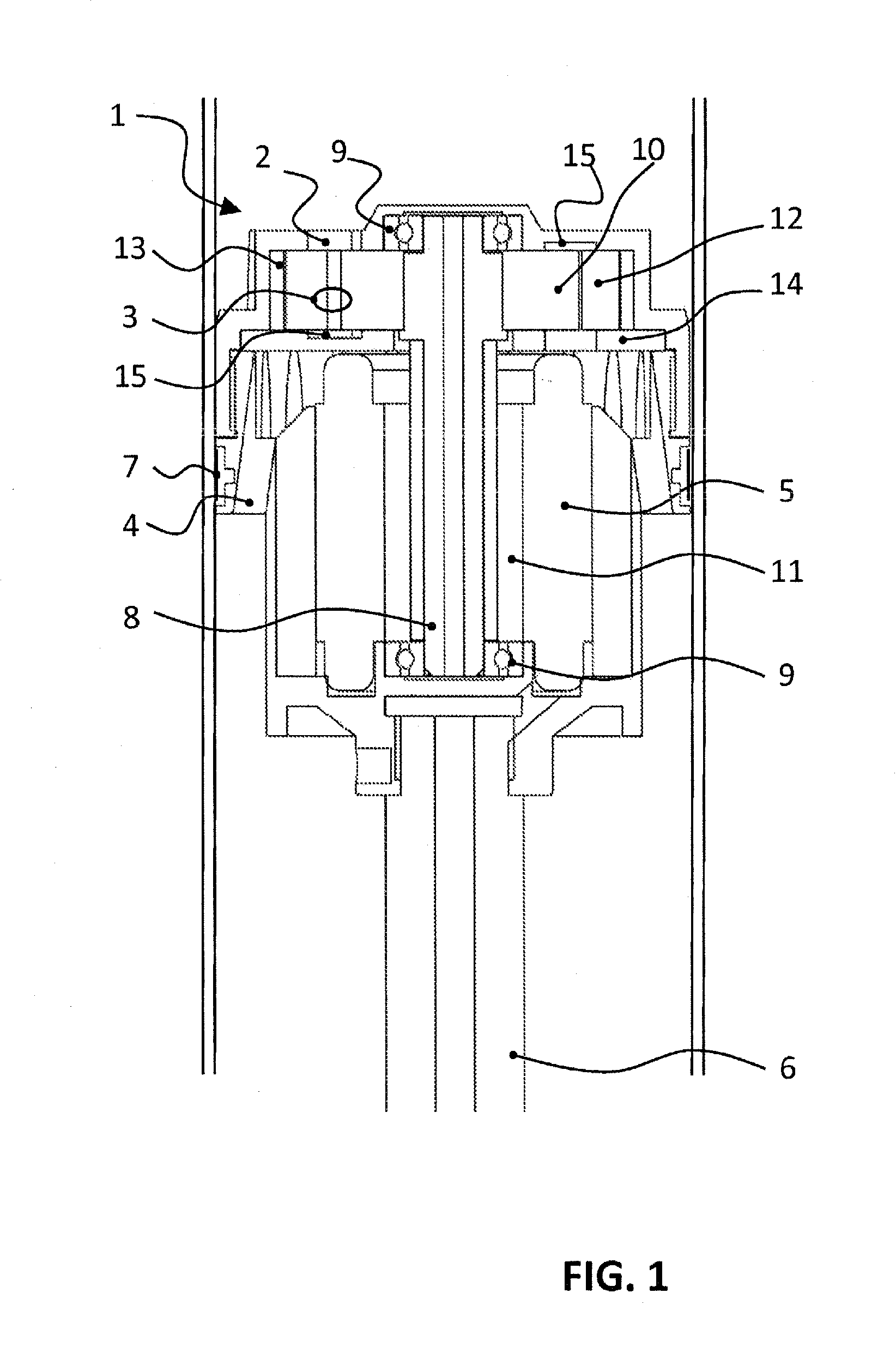
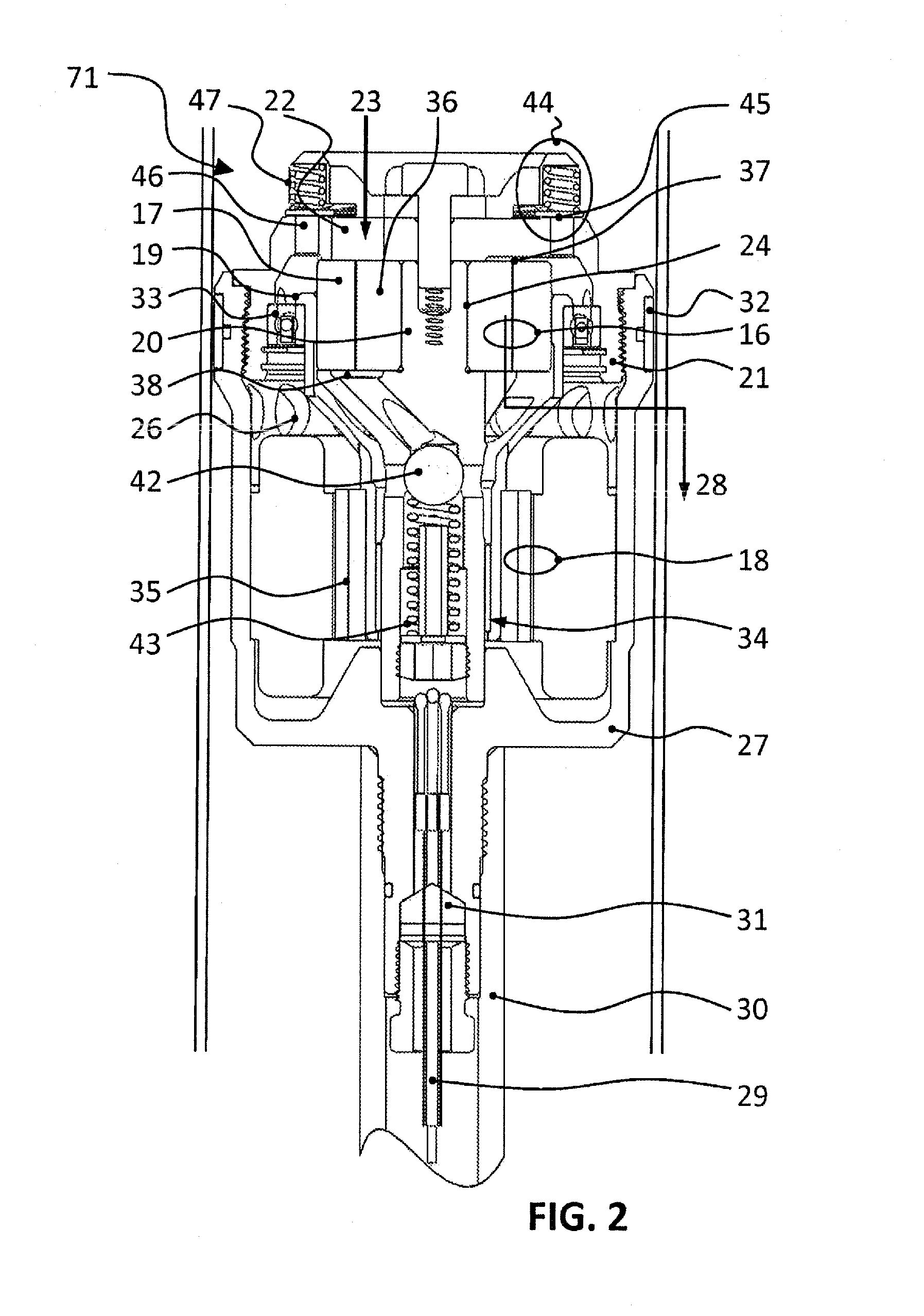
[0036]Some aspects of the system relate to an integrated energy generator that is capable of harnessing energy from high force but relatively low velocity movement, without the need for external fluid circuits which typically lower system efficiency, and introduce durability problems and added manufacturing costs. Several embodiments utilize traditional damper configurations and components, with improvements focused on integration of energy harvesting componentry and valving on the piston head and elsewhere in the housing. While “damper” is used in reference to the system, it should be noted that the invention is not limited to oscillatory systems nor is it merely an energy-extracting device, as it can be actuated as well. Embodiments of the described integrated energy generator may include a housing and a piston that moves at least partially through a compression stroke when compressed. The piston may additionally move at least partially through an extension stroke when extended (i...


PUM


Abstract

A linear energy harvesting device that includes a housing and a piston that moves at least partially through the housing when it is compressed or extended from a rest position. When the piston moves, hydraulic fluid is pressurized and drives a hydraulic motor. The hydraulic motor drives an electric generator that produces electricity. Both the motor and generator are central to the device housing. Exemplary configurations are disclosed such as monotube, twin-tube, tri-tube and rotary based designs that each incorporates an integrated energy harvesting apparatus. By varying the electrical characteristics on an internal generator, the kinematic characteristics of to the energy harvesting apparatus can be dynamically altered. In another mode, the apparatus can be used as an actuator to create linear movement. Applications include vehicle suspension systems (to act as the primary damper component), railcar bogie dampers, or industrial applications such as machinery dampers and wave energy harvesters, and electro-hydraulic actuators.

Description

CROSS-REFERENCE TO RELATED APPLICATIONS[0001]This application is a continuation of U.S. application Ser. No. 13 / 704,138, filed Dec. 13, 2012, which is a national stage filing under 35 U.S.C. §371 of international application PCT / US2011 / 040654, filed Jun. 16, 2011, which claims the benefit under 35 U.S.C. §119(e) of U.S. provisional application Ser. No. 61 / 355,186, filed Jun. 16, 2010 and U.S. provisional to application Ser. No. 61 / 467,161, filed Mar. 24, 2011, the disclosures of which are incorporated by reference herein in its entirety.BACKGROUND[0002]1. Field[0003]Aspects relate to damper systems and linear and rotary energy capture systems that capture energy associated with relative motion.[0004]2. Discussion of Related Art[0005]A typical damper dissipates energy associated with motion. Linear dampers typically include a housing with a piston positioned inside that is movable in both a compression stroke and an extension stroke. An orifice is positioned in the piston. The motion...

Claims


Application Information

Patent Timeline
IPC IPC(8): F03G7/08
CPCF01C1/103F01C9/002B60G2400/252F03C1/26F03G7/08F01C13/00B60G11/265B60G13/14B60G17/08
Inventor TUCKER, CLIVEWENDELL, ROSSANDERSON, ZACKARY M.MOEN, EVANSCHNEIDER, JOHANNESJACKOWSKI, ZACHARY J.MORTON, SEAN
Owner CLEARMOTION INC
Why Eureka
Try Eureka