Duplexer

a technology of duplexers and filters, applied in piezoelectric/electrostrictive devices, piezoelectric/electrostrictive/magnetostrictive devices, electrical apparatus, etc., can solve problems such as signal loss and ripple in pass characteristics of filters

Inactive Publication Date: 2013-06-13
TAIYO YUDEN KK
View PDF11 Cites 15 Cited by
  • Summary
  • Abstract
  • Description
  • Claims
  • Application Information

AI Technical Summary

Benefits of technology

[0006]According to an aspect of the present invention, there is provided a duplexer including: a first filter of which a first end is coupled to a common terminal, and a second end is coupled to a first terminal; and a second filter having a passband higher than a passband of the first filter, a first end of the second filter being coupled to the common terminal, and a second end being coupled to a second terminal, wherein a phase shifter is located neither between the first filter and the common terminal nor between the second filter and the common terminal, the second filter is a ladder-type filter including piezoelectric thin film resonators connected in a ladder shape, a propagation constant in a direction perpendicular to a thickness direction of a piezoelectric thin film included in the piezoelectric thin film resonator is a real number at frequencies lower than a resonance frequency of the piezoelectric thin film resonator, and a resonator at a first stage as viewed from a side of the common terminal is a parallel resonator in the second filter.

Problems solved by technology

Insertion of the phase shifter may cause loss of signal.
However, when impedance matching is performed without using the phase shifter, a ripple may occur in pass characteristics of the filter.

Method used


Image

  • Duplexer
  • Duplexer
  • Duplexer

Examples


first embodiment

[0124]A description will now be given of embodiments of the present invention based on the above discussion. A first embodiment describes a case where a piezoelectric thin film resonator has dispersion characteristics of frequency decreasing type. FIG. 34A is a circuit diagram illustrating a duplexer in accordance with the first embodiment.

[0125]As illustrated in FIG. 34A, a duplexer 100a of the first embodiment includes a transmission filter F13 (first filter), a reception filter F14 (second filter), an antenna terminal Ant (common terminal), a transmission terminal Tx (first terminal), and a reception terminal Rx (second terminal). A first end of the transmission filter F13 is connected to the antenna terminal Ant, and a second end is connected to the transmission terminal Tx. A first end of the reception filter F14 is connected to the antenna terminal Ant, and a second end is connected to the reception terminal Rx. The transmission filter F13 and the reception filter F14 are inte...

second embodiment

[0140]A second embodiment describes a case where the piezoelectric thin film resonator has dispersion characteristics of frequency increasing type. FIG. 35B is a circuit diagram illustrating a duplexer in accordance with the second embodiment. A description of components same as those already described in FIG. 34A through FIG. 35B is omitted.

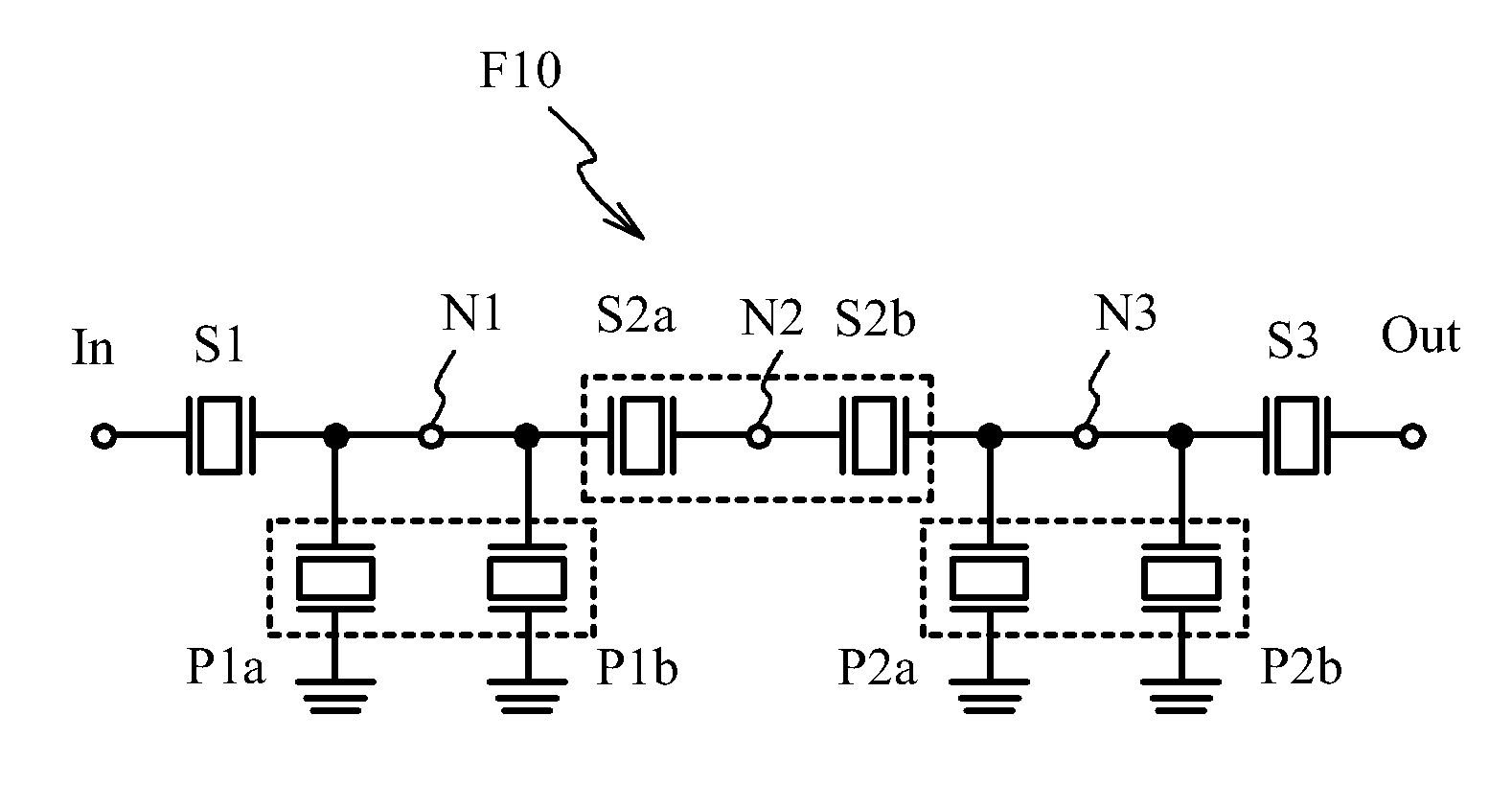
[0141]As illustrated in FIG. 35B, a reception filter F17 is an n-stage ladder-type filter including the series resonators S1 through Sn and the parallel resonators P1 through Pn. A resonator at the first stage as viewed from the antenna terminal Ant side is the series resonator S1 in the reception filter F17. In addition, the reception filter F17 is a filter that makes the impedance of the reception filter F17 close to infinity in the passband of the transmission filter by performing the phase rotation at the reception filter of the comparative example. That is to say, the reception filter F17 corresponds to the case presented in Table 1. The se...

third embodiment

[0144]A third embodiment uses a duplexer in an RF (Radio Frequency) module. FIG. 36 is a block diagram illustrating an RF module in accordance with the third embodiment.

[0145]As illustrated in FIG. 36, an RF module 400 includes an antenna 104, an antenna switch 402, a duplexer bank 404, and an amplifier module 406. The RF module 400 is an RF module for, for example, mobile phones, and supports multiple communication methods such as GSM (Global System for Mobile Communication) communication method and W-CDMA communication method. For GSM, the RF module 400 supports 850 MHz band (GSM850), 900 MHz band (GSM900), 1800 MHz band (GSM1800), and 1900 MHz band (GSM1900). The antenna 104 receives both transmission and reception signals of GSM and W-CDMA.

[0146]The duplexer bank 404 includes duplexers 404a, 404b and 404c. The duplexers supports respective communication methods. The antenna switch 402 selects a duplexer, which supports the communication method with which signals are to be transm...


PUM


Abstract

A duplexer includes: a first filter of which first and second ends connect to a common terminal and a first terminal respectively; and a second filter having a passband higher than that of the first filter, a first end and second end thereof connecting to the common terminal and a second terminal respectively, wherein a phase shifter is located neither between the first filter and the common terminal nor between the second filter and the common terminal, the second filter is a ladder-type filter including piezoelectric thin film resonators connected in a ladder shape, a propagation constant in a direction perpendicular to a thickness direction of a piezoelectric thin film in the piezoelectric thin film resonator is a real number at frequencies lower than a resonance frequency of the piezoelectric thin film resonator, and a resonator at a first stage is a parallel resonator in the second filter.

Description

CROSS-REFERENCE TO RELATED APPLICATION[0001]This application is a continuation of and claims priority to International Patent Application No. PCT / JP2011 / 058926 filed Apr. 8, 2011, which claims priority to Japanese Patent Application No. 2010-233640 filed on Oct. 18, 2010, subject matter of these patent documents is incorporated by reference herein in its entirety.FIELD[0002]A certain aspect of the present invention relates to duplexers.BACKGROUND[0003]In recent years, mobile communication devices such as mobile phones and mobile information terminals have rapidly spread. Duplexers, especially, high-frequency duplexers are used in mobile communication devices to prevent reception and transmission signals from interfering with each other. A duplexer is commonly composed of a transmission filter and a reception filter as a package to downsize the mobile communication devices. A ladder-type filter may be used as a low-loss filter constituting the duplexer. The ladder-type filter is a fi...

Claims


Application Information

Patent Timeline
Patent Type & Authority Applications(United States)
IPC IPC(8): H03H9/70H01L41/09H01L41/187H03H9/17H03H9/54H04B1/3822H04B1/52
CPCH03H9/605H03H9/706H04B1/0057H03H9/175H03H9/132H03H9/173H03H9/70H03H9/02015
Inventor HARA, MOTOAKIINOUE, SHOGOIWAKI, MASAFUMITSUTSUMI, JUN
Owner TAIYO YUDEN KK
Why Eureka
Try Eureka