High-frequency signal transmission line and electronic apparatus

a technology of high-frequency signal transmission line and electronic equipment, which is applied in the direction of waveguides, waveguide type devices, high-frequency circuit adaptations, etc., can solve the problem of difficulty in obtaining the space required for a coaxial cable having a circular cross section, and achieve the effect of convenient bending

Active Publication Date: 2013-06-13
MURATA MFG CO LTD
View PDF0 Cites 13 Cited by
  • Summary
  • Abstract
  • Description
  • Claims
  • Application Information

AI Technical Summary

Benefits of technology

[0009]Preferred embodiments of the present invention provide a high-frequency signal transmission line that can be easily bent and can significantly reduce and prevent deviation of a characteristic impedance of a signal line included therein from a predetermined characteristic impedance, and also provide an electronic apparatus.
[0013]According to various preferred embodiments of the present invention, a signal line can be easily bent, and the deviation of the characteristic impedance of the signal line from a predetermined characteristic impedance can be significantly reduced and prevented.

Problems solved by technology

Accordingly, in such a high-frequency apparatus, it is difficult to obtain the space required for a coaxial cable having a circular cross section.

Method used


Image

  • High-frequency signal transmission line and electronic apparatus
  • High-frequency signal transmission line and electronic apparatus
  • High-frequency signal transmission line and electronic apparatus

Examples


first preferred embodiment

[0057]A high-frequency signal transmission line and an electronic apparatus according to the first preferred embodiment of the present invention will be described below with reference to the accompanying drawings.

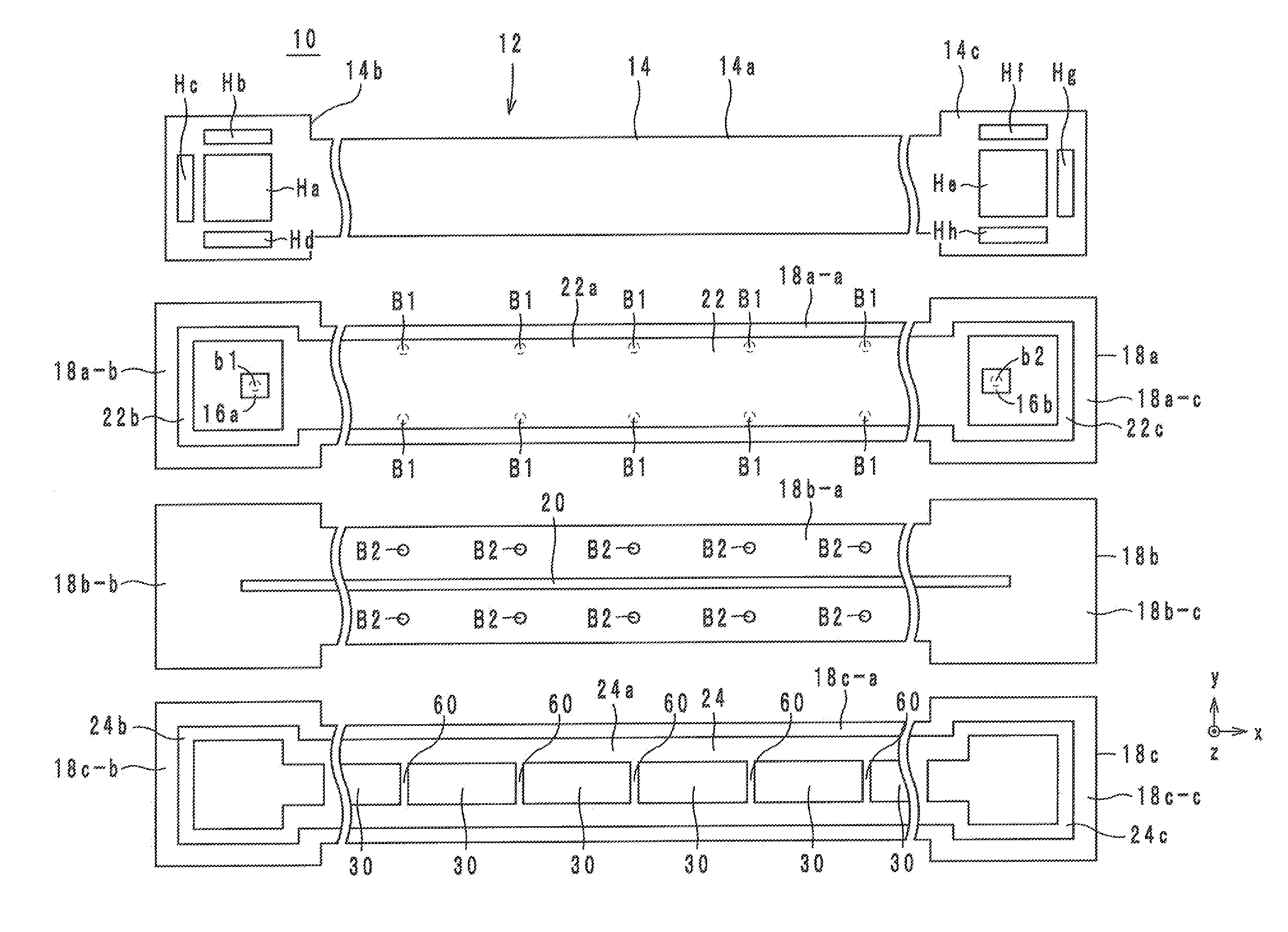
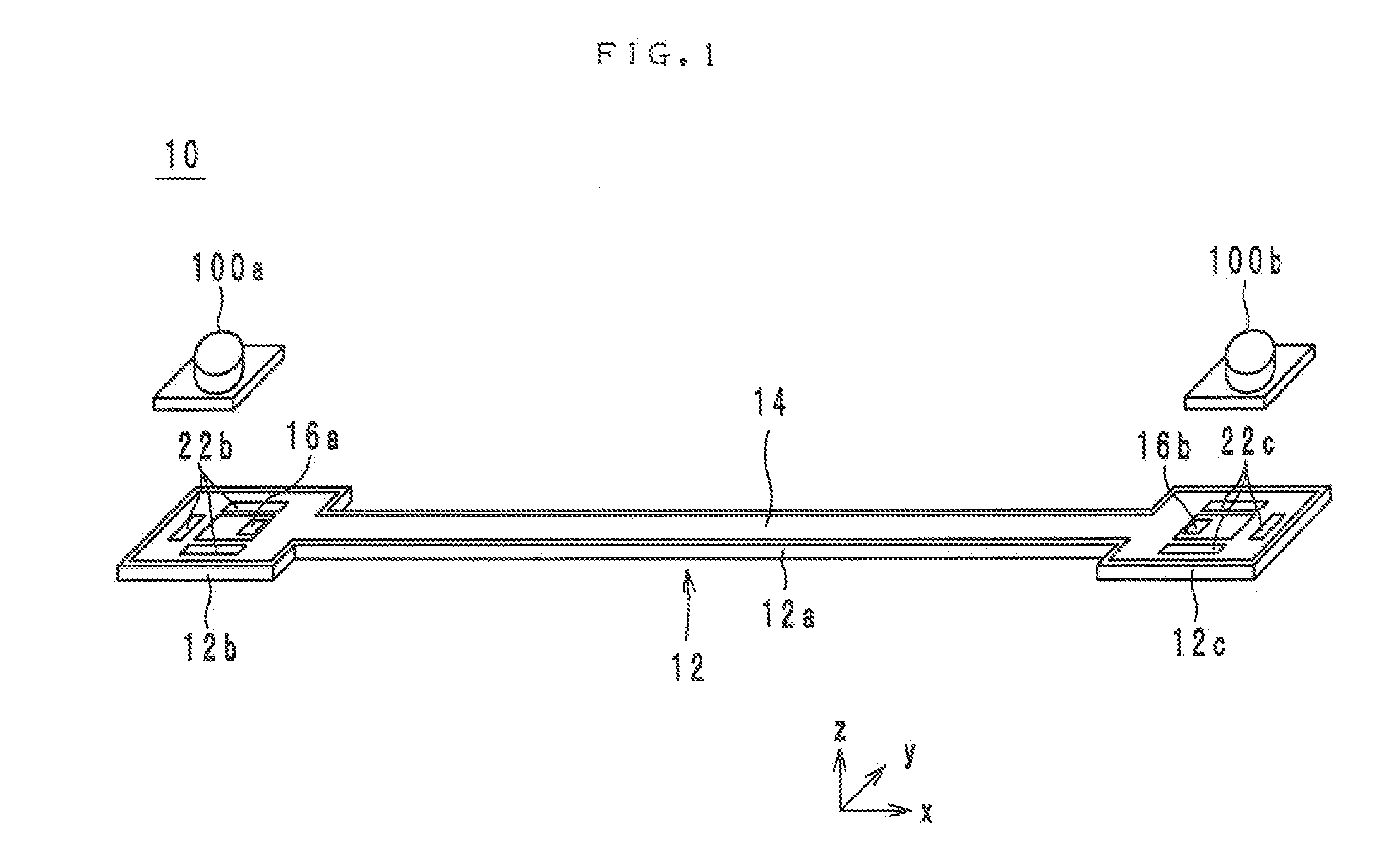
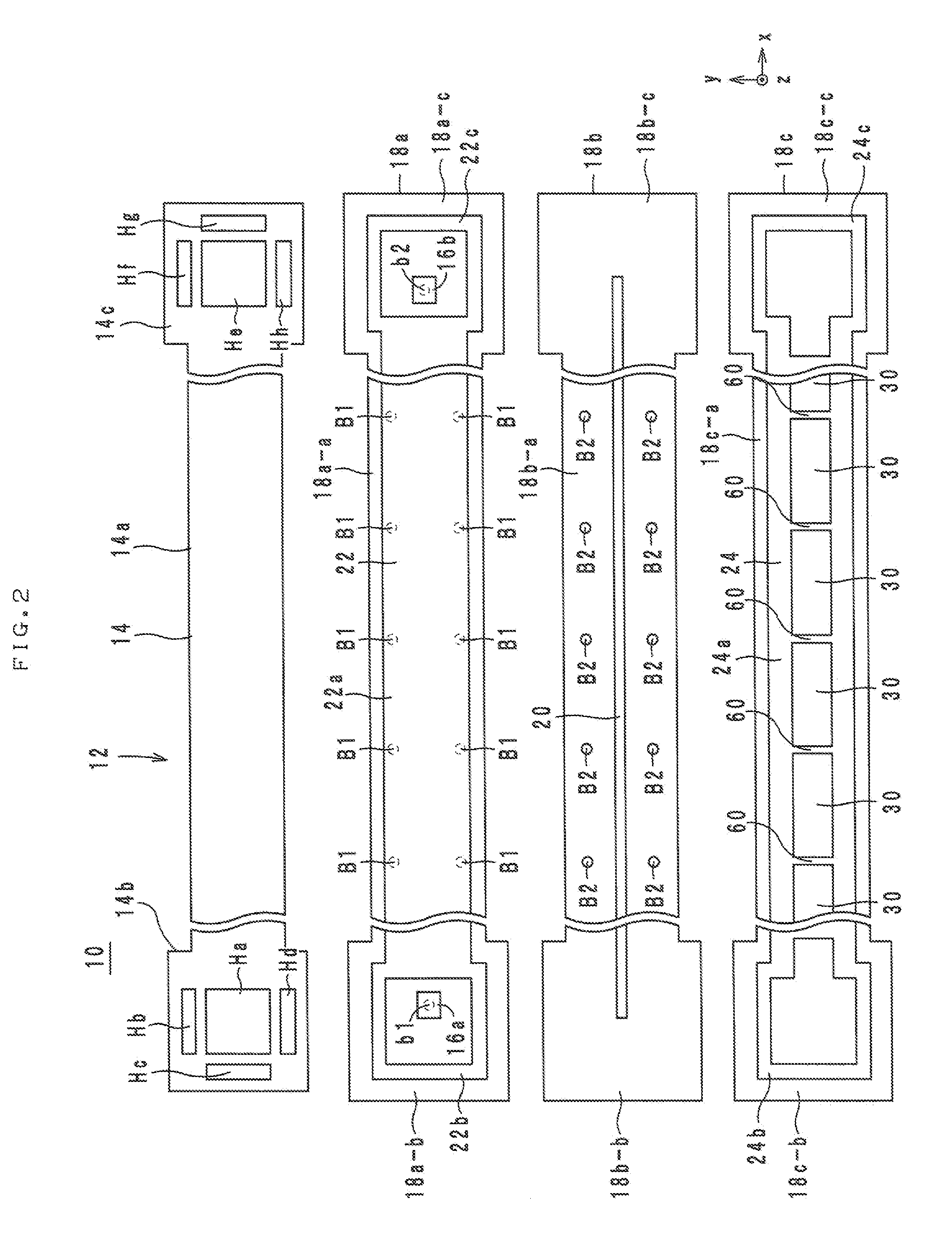
[0058]The structure of a high-frequency signal transmission line according to the first preferred embodiment of the present invention will be described below with reference to the accompanying drawings. FIG. 1 is an external perspective view of a high-frequency signal transmission line 10 according to the first preferred embodiment of the present invention. FIG. 2 is an exploded view of a dielectric body 12 in the high-frequency signal transmission line 10 illustrated in FIG. 1. FIG. 3 is a cross-sectional view of the high-frequency signal transmission line 10 illustrated in FIG. 1. FIG. 4 is a cross-sectional view of the high-frequency signal transmission line 10. FIGS. 5A and 5B are an external perspective view and a cross-sectional view of a connector 100b in the high-fr...

second preferred embodiment

[0162]A high-frequency signal transmission line and an electronic apparatus according to the second preferred embodiment of the present invention will be described below with reference to the accompanying drawings.

[0163]The structure of a high-frequency signal transmission line according to the second preferred embodiment of the present invention will be described below with reference to the accompanying drawings. FIG. 21 is an external perspective view of a high-frequency signal transmission line 10g according to the second preferred embodiment of the present invention. FIG. 22 is an exploded view of the dielectric body 12 in the high-frequency signal transmission line 10g illustrated in FIG. 21. FIG. 23 is a cross-sectional view of the high-frequency signal transmission line 10g illustrated in FIG. 21. FIG. 24 is a cross-sectional view of the high-frequency signal transmission line 10g. Referring to FIGS. 21 to 24, a lamination direction in the high-frequency signal transmission l...


PUM


Abstract

An easily bendable high-frequency signal transmission line includes a dielectric body including a protection layer and dielectric sheets laminated on each other, a surface and an undersurface. A signal line is a linear conductor disposed in the dielectric body. A ground conductor is disposed in the dielectric body, faces the signal line via the dielectric sheet, and continuously extends along the signal line. A ground conductor is disposed in the dielectric body, faces the ground conductor via the signal line sandwiched therebetween, and includes a plurality of openings arranged along the signal line. The surface of the dielectric body on the side of the ground conductor with respect to the signal line is in contact with a battery pack.

Description

BACKGROUND OF THE INVENTION[0001]1. Field of the Invention[0002]The present invention relates to high-frequency signal transmission lines and electronic apparatuses, and, more particularly, to a high-frequency signal transmission line including a signal line and ground conductors facing the signal line and an electronic apparatus.[0003]2. Description of the Related Art[0004]As a high-frequency transmission line for connecting high-frequency circuits, a coaxial cable is generally used. Since coaxial cables are easily deformed (bent) and are inexpensive, they are widely used.[0005]In recent years, high-frequency apparatuses such as mobile communication terminals have been miniaturized. Accordingly, in such a high-frequency apparatus, it is difficult to obtain the space required for a coaxial cable having a circular cross section. A high-frequency signal transmission line obtained by forming a strip line in a flexible laminate is therefore sometimes used.[0006]Triplate strip lines have...

Claims


Application Information

Patent Timeline
Patent Type & Authority Applications(United States)
IPC IPC(8): H01P3/10
CPCH05K1/0219H01P3/08H05K1/0242H05K1/0253H05K1/028H05K1/0393H05K1/113H05K2201/09618H05K2201/0969H05K2201/09727H01P1/20363H01P3/085H01P3/121H01P3/026H04B15/00H01P3/10H03H7/38H05K1/025H01P3/003H05K1/0225H01L2224/16225H01L2924/19105H01P5/08H05K1/02
Inventor KATO, NOBORUTAGO, SHIGERUSASAKI, JUNKURITA, JUNICHISASAKI, SATOSHI
Owner MURATA MFG CO LTD
Why Eureka
Try Eureka