Image forming apparatus

a technology of forming apparatus and image, which is applied in the direction of electrographic process apparatus, instruments, optics, etc., can solve the problems of degrading image quality, photoreceptors are likely to be affected by varying loads on the developer during visualization,

Inactive Publication Date: 2013-06-13
KONICA MINOLTA BUSINESS TECH INC
View PDF2 Cites 9 Cited by
  • Summary
  • Abstract
  • Description
  • Claims
  • Application Information

AI Technical Summary

Benefits of technology

[0008]An image forming apparatus according to a first aspect of the present invention includes: a driving source configured to generate power; a first rotator configured to be drivingly rotated by the power generated by the driving source; a first power transmission system configured to transmit the power from the driving source to the first rotator; a second rotator configured to be drivingly rotated by the power generated by the driving source; and a second power transmission system configured to transmit the power to the second rotator from the first power transmission system or from the first rotator. A damper to damp oscillation is disposed between the first power transmission system and the second power transmission system or between the first rotator and the second power transmission system. The damper has a torsion spring constant and a torsion viscous damping constant making a maximum positional change value of the first rotator equal to or smaller than a predetermined positional change value.

Problems solved by technology

However, according to the configuration employed for the process cartridge of Japanese Unexamined Patent Application Publication No. 1995-140744, the drum gear secured to the photoreceptor meshes with the roller gear secured to the developer (developing roller), and thus the photoreceptor is likely to be affected by varying loads on the developer during the visualization.
As a result, a band shaped image blurring (banding) is produced on the image, and thus the image quality is degraded.
The variations in rotation rate (varying rotation rates) of the photoreceptor might be caused by various causes other than the varying loads on the developer, for example variations in rotation rate of a driving source provided on a side of a main body and a transmission error produced by meshing between gears.

Method used


Image

  • Image forming apparatus
  • Image forming apparatus
  • Image forming apparatus

Examples


first embodiment

(2) First Embodiment of Power Transmission Structure, Directed to Image Forming Unit

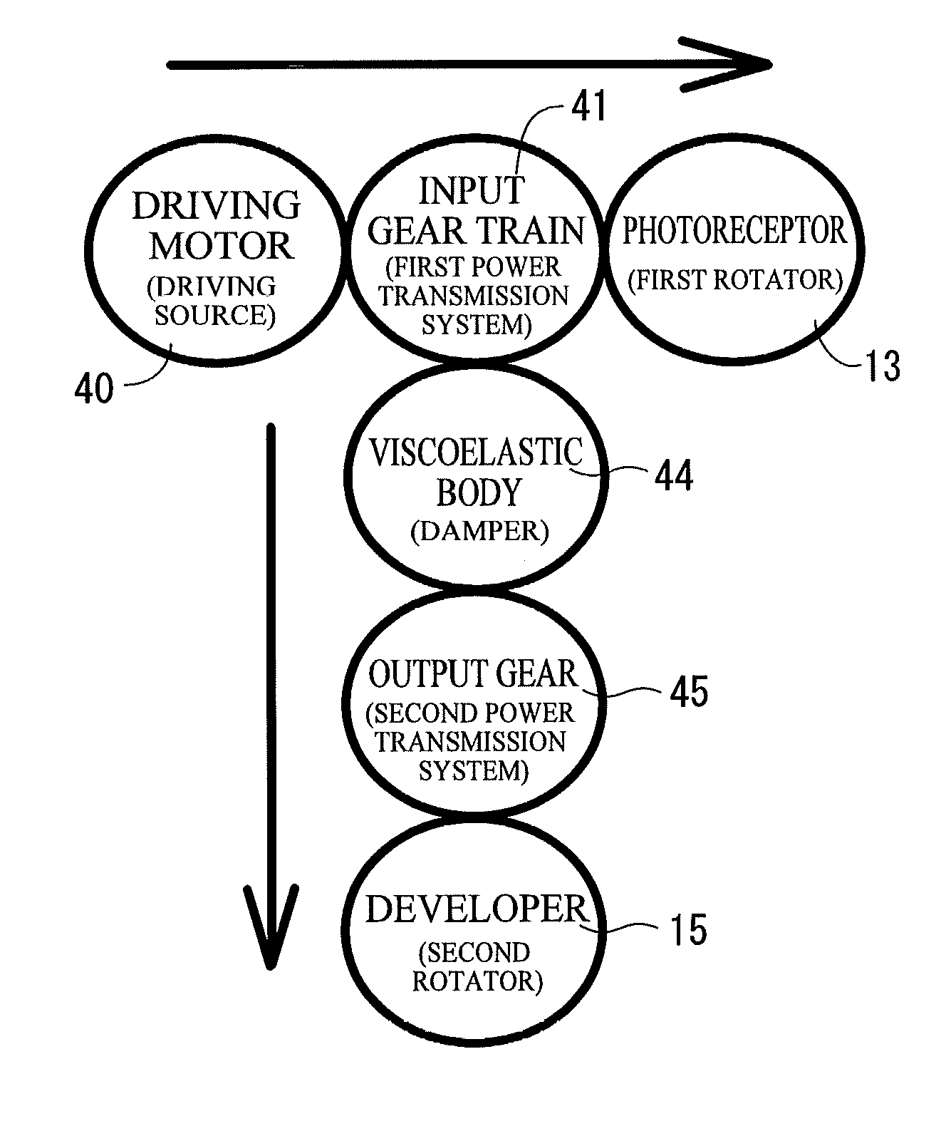
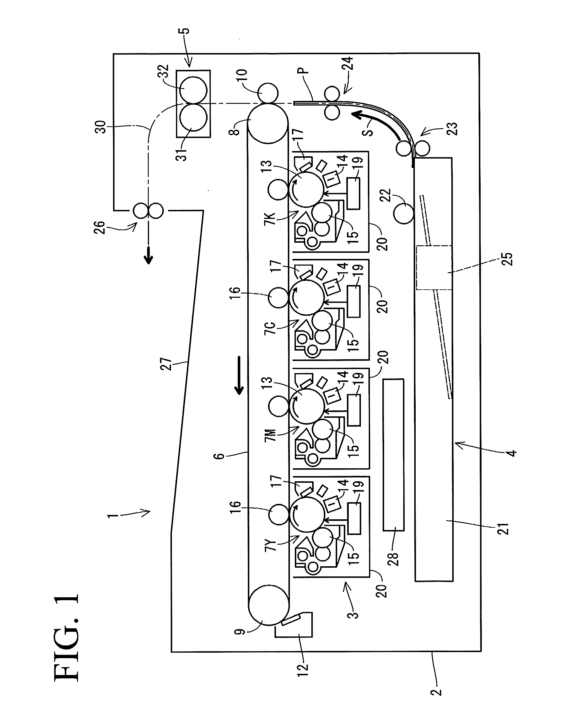
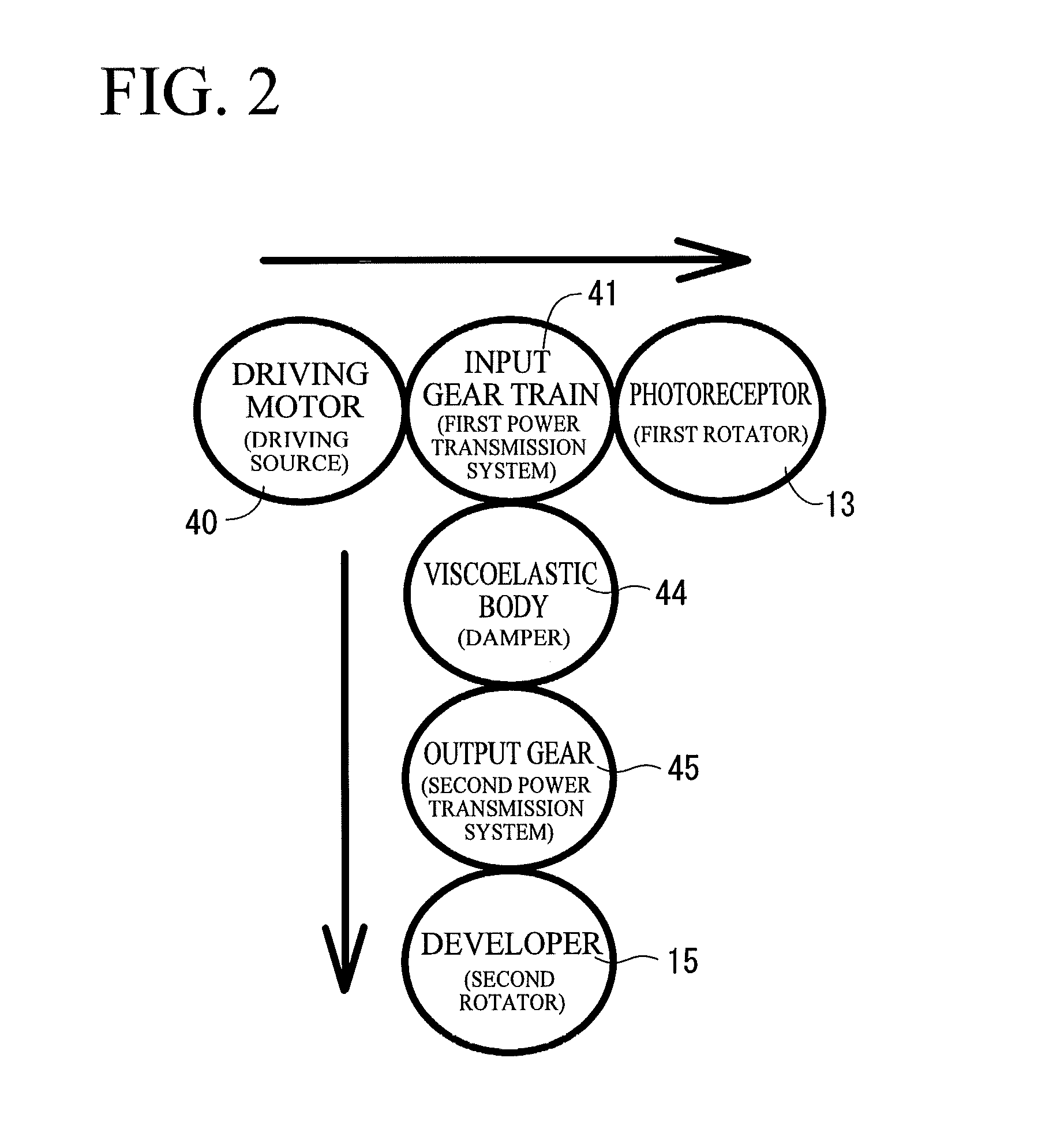
[0034]Referring to FIG. 2 and FIG. 3, a first embodiment of a power transmission structure directed to the image forming unit 7 will be described below. The printer 1 includes, on a side of the casing 2, a driving motor 40 serving as a driving source to generate power. In the first embodiment, the power generated by the driving motor 40 is branched into two directions, namely, to the photoreceptor 13 serving as a first rotator and to the developer 15 serving as a second rotator (see FIG. 2 and FIG. 3).

[0035]The power generated by the driving motor 40 is first transmitted to an input gear train 41 serving as a first power transmission system. The input gear train 41 meshes with a photoreceptor gear 42 coupled to a rotary shaft 13a of the photoreceptor 13, to transmit power to the photoreceptor gear 42. Thus, the photoreceptor 13 integrally rotates with the photoreceptor gear 42. An output branching ge...

second embodiment

(3) Second Embodiment of Power Transmission Structure, Directed to Image Forming Unit

[0047]Referring to FIG. 8 and FIG. 9, a second embodiment of the power transmission structure, which is directed to the image forming unit 7, will be described. In the second embodiment, the power generated by a driving motor 50 is transmitted to the photoreceptor 13 and the developer 15 in this order (see FIG. 8). A photoreceptor gear 52 is a component of the second power transmission system and is unremovably secured to the rotary shaft 13a of the photoreceptor 13. A viscoelastic body 54 serving as a damper is provided between the photoreceptor gear 52 and the rotary shaft 13a. An input gear train 51 serving as the first power transmission system meshes with the photoreceptor gear 52 to transmit power to the photoreceptor gear 52. The photoreceptor gear 52 is power transmittably coupled to the developer 15 through an output relay gear 55. The viscoelastic body 54 may be similar to that in the firs...

third embodiment

(4) Third Embodiment of Power Transmission Structure, Directed to Periphery of Intermediate Transfer Belt

[0048]A third embodiment of the power transmission structure, which is directed to the periphery of the intermediate transfer belt 6, will be described by referring to FIG. 10. In the third embodiment, the power generated by a driving motor 60, which is a driving source disposed on a side of the casing 2 of the printer 1, is branched into two directions, namely, to the driving roller 8 serving as the first rotator and to the fixing device 5 (which includes the fixing roller 31 and the pressure roller 32) serving as the second rotator. That is, part of the power generated by the driving motor 60 is transmitted to the driving roller 8 through a first power transmission system 61, which includes an input gear train. The rest of the power is transmitted to the fixing device 5 from the first power transmission system 61 through a viscoelastic body 64 serving as a damper and a second p...


PUM


Abstract

An image forming apparatus includes: a driving source configured to generate power; a first rotator configured to be drivingly rotated by the power generated by the driving source; a first power transmission system configured to transmit the power from the driving source to the first rotator; a second rotator configured to be drivingly rotated by the power generated by the driving source; and a second power transmission system configured to transmit the power to the second rotator from the first power transmission system. A damper having a torsion spring constant and a torsion viscous damping constant making a maximum positional change value of the first rotator equal to or smaller than a predetermined positional change value is disposed between the first power transmission system and the second power transmission system.

Description

CROSS-REFERENCE TO RELATED APPLICATIONS[0001]The present application claims priority under 35 U.S.C. §119 to Japanese Patent Application No. 2011-269787, filed Dec. 9, 2011. The contents of this application are incorporated herein by reference in their entirety.BACKGROUND OF THE INVENTION[0002]1. Field of the Invention[0003]The present invention relates to an image forming apparatus including copiers, printers, fax machines, and multi-function machines integrally incorporating copy, printing and fax capabilities.[0004]2. Discussion of the Background[0005]Electrographic image forming apparatuses obtain images by forming an electrostatic latent image on the surface of a rotating photoreceptor, visualizing the electrostatic latent image into a toner image on a developer, and electrostatically transferring the toner image onto a recording medium. Japanese Unexamined Patent Application Publication No. H7-140744 discloses an electrographic image forming apparatus of this kind. In the elec...

Claims


Application Information

Patent Timeline
Patent Type & Authority Applications(United States)
IPC IPC(8): G03G15/00
CPCG03G15/00G03G2215/0132G03G21/1857
Inventor OOMOTO, NOBORUYOSHIKAWA, SHOICHISEKIOKA, TADAYASUTOSO, YOSHIYUKIFUJIWARA, TAKASHIMIYAGAWA, NAOKI
Owner KONICA MINOLTA BUSINESS TECH INC
Why Eureka
Try Eureka