
Compact compliant centering support for squeeze film damper

a technology of squeeze film and centering support, which is applied in the direction of elastic bearings, rigid support of bearings, machines/engines, etc., can solve the problems of compromising the performance of squeeze film dampers, bos patent does not appear to disclose an apparatus or method for centering rotors, and bos patent does not appear to disclose an apparatus or method for providing additional suppor

Inactive Publication Date: 2006-04-20
HONEYWELL INT INC
View PDF20 Cites 18 Cited by
  • Summary
  • Abstract
  • Description
  • Claims
  • Application Information

AI Technical Summary

Problems solved by technology

To counteract the tendency for the rotating assembly to operate off center, thus compromising the performance of the squeeze film damper, various conventional designs attempt to use a centering feature to maintain a uniform squeeze film damper thickness.
However, the Bos patent does not appear to disclose an apparatus or method for centering a rotor or eliminating maneuver deflection of the rotor.
Furthermore, the Bos patent does not appear to disclose an apparatus or method for providing additional viscous damping.

Method used


Image

  • Compact compliant centering support for squeeze film damper
  • Compact compliant centering support for squeeze film damper
  • Compact compliant centering support for squeeze film damper

Examples


Embodiment Construction

[0016] The following detailed description is of the best currently contemplated modes of carrying out the invention. The description is not to be taken in a limiting sense, but is made merely for the purpose of illustrating the general principles of the invention, since the scope of the invention is best defined by the appended claims.

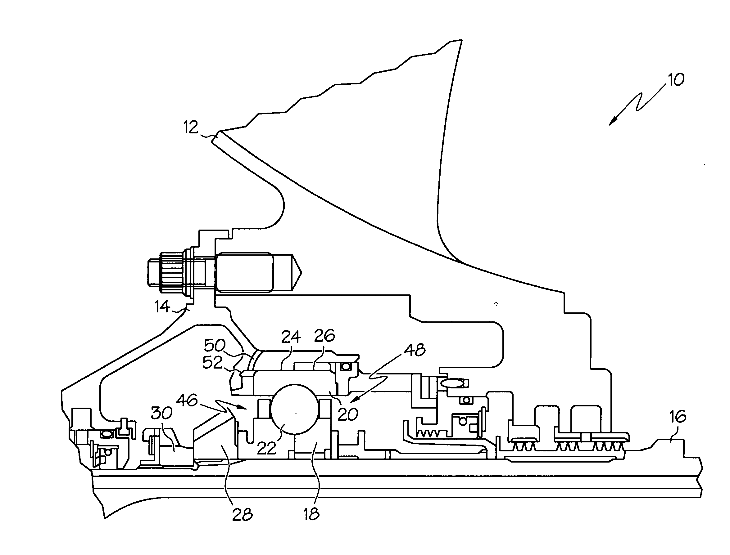
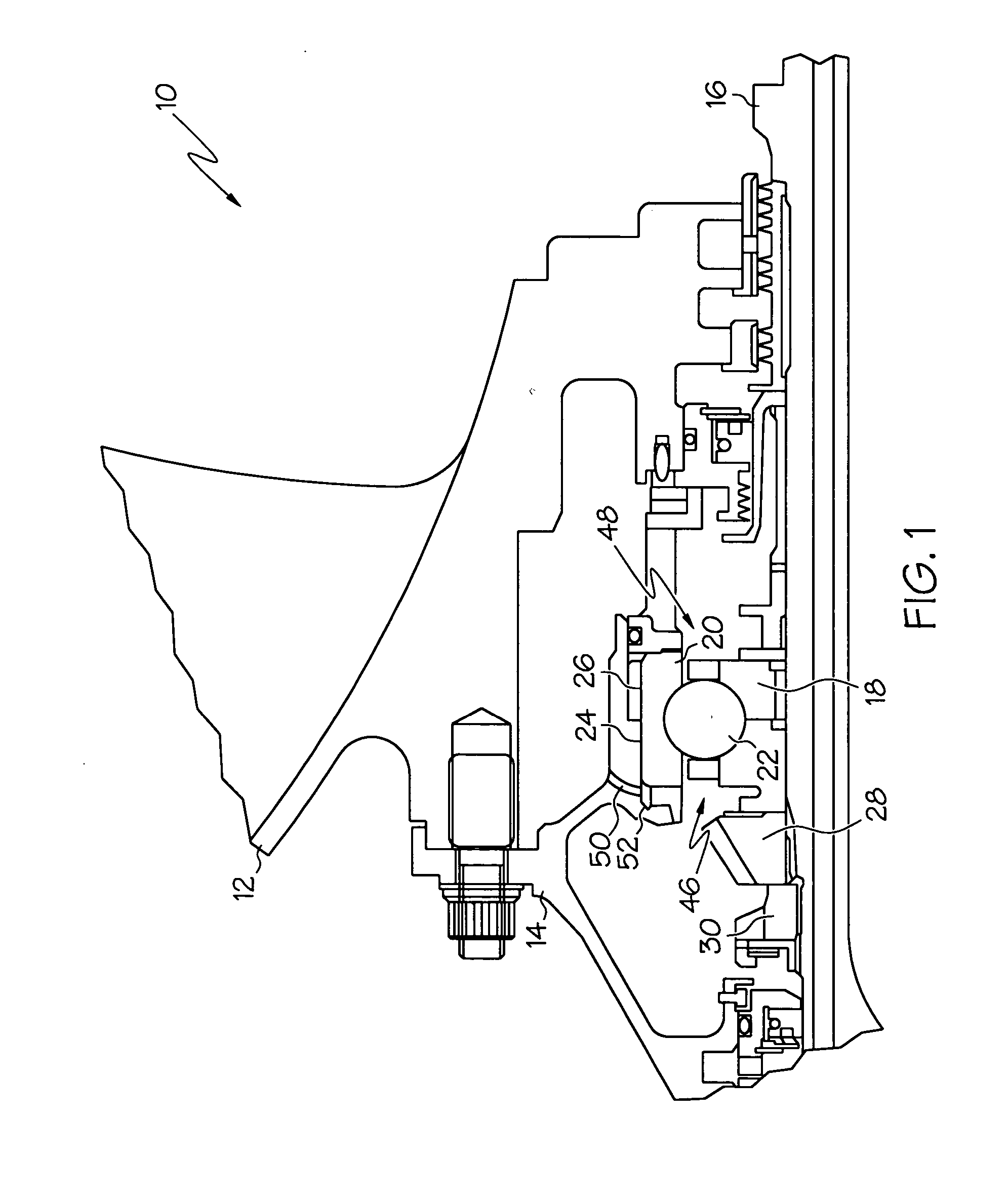
[0017] Broadly, the present invention provides a centering feature to the bearing of a turbomachine (such as found in aircraft, land vehicles, space craft, generation equipment, and other high speed rotating equipment uses) that eliminates unstable vibrations and dampens synchronous vibrations. Unlike conventional designs that use heavyweight components to center the squeeze film damper, the present invention provides a compact compliant centering support for the squeeze film damper interfaces between a component, such as a bearing assembly outer race, and an outer support structure (such as an engine case or frame).

[0018] The compact design of the p...


PUM


Abstract

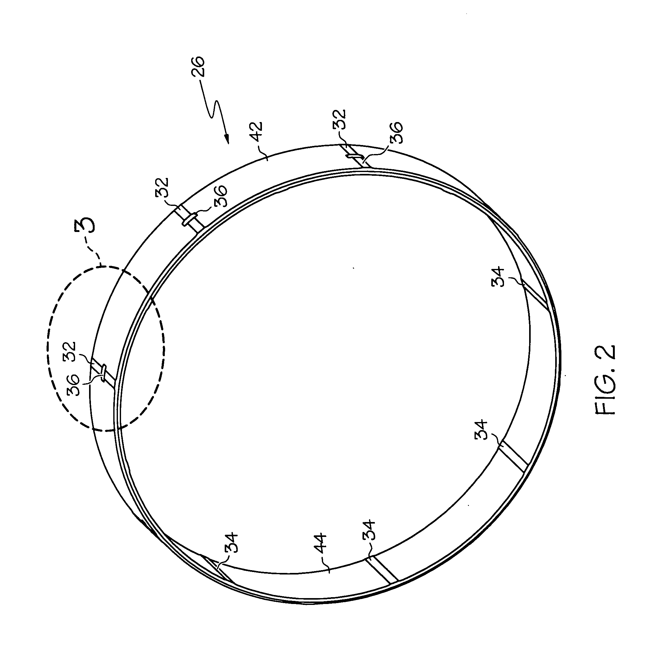
The present invention provides a centering feature to the bearing assembly of a turbomachine to provide optimum operating characteristics of the squeeze film damper. Unlike conventional bearing centering methods and apparatus, a compact compliant centering support for the squeeze film damper interfaces between a bearing outer race, and an outer support structure. The compact design is lightweight and inexpensive, can be retrofitted easily to an existing turbomachine, such as a turbine and compressor, for improved rotor dynamic performance. The compact compliant centering support damper may be comprised of a ring with bumpers spaced around the circumference at the inside and outside diameters to form spring elements between the bumpers. The centering support may lift the rotor inside the squeeze film cavity and may eliminate rotor weight effect on the damper performance. The centering support may be offset in the vertical direction to center the rotor under 1 g deflection to eliminate rub at the 6 o'clock location of a compressor or turbine shroud. Tangential grooves may be provided on the centering support outer bumpers to allow oil to squeeze out when the centering support is deflected to provide additional viscous damping. The outer bumper height may be controlled to limit maneuver deflection of the rotor.

Description

BACKGROUND OF THE INVENTION [0001] This invention relates to turbomachine, and more specifically, to the bearing support assembly that transmits the vibration force from the rotor assembly to the support structure. [0002] A turbomachine includes rotating components such as a fan, a compressor, and a turbine. The components are clamped either by a shaft or by bolted flange joints into a rotor assembly. During high-speed rotation of this rotor assembly, forces are transmitted from the rotor assembly to the support structure. To damp the effect of these transmitted forces, a film of oil (“squeeze film”) may be confined between the rotor assembly and the support structure. The oil in the squeeze film is under pressure and acts as a damper. Adequate damping requires that the squeeze film not be too thick or too thin. The rotating rotor assembly may not remain concentric, with respect to the squeeze film cavity, because of rotor assembly movement during acceleration, deceleration, or stea...

Claims


Application Information

Patent Timeline
Patent Type & Authority Applications(United States)
IPC IPC(8): F16C27/00
CPCF01D25/164F16C27/04F16F15/0237Y02T50/671F16C2360/23F16C19/06F16C27/045Y02T50/60
Inventor ALAM, MOHSIULSPENCER, DOUG K.CHARLESTON, SHARI L.TALBERT, PAUL B.JANKOWICH, EDWARD M.JOHNSON, MATTHEW D.
Owner HONEYWELL INT INC
Learn More