Arrangement for introducing a liquid medium into exhaust gases from a combustion engine

a technology of liquid medium and combustion engine, which is applied in the direction of machines/engines, mechanical equipment, transportation and packaging, etc., can solve the problems of lumps over time blocking the exhaust line, and it is difficult to avoid the contact of urea solution supplied with the internal wall surface of the exhaust line in an unvaporised state,

a technology of liquid medium and combustion engine, which is applied in the direction of machines/engines, mechanical equipment, transportation and packaging, etc., can solve the problems of lumps over time blocking the exhaust line, and it is difficult to avoid the contact of urea solution supplied with the internal wall surface of the exhaust line in an unvaporised state,

US20130152558A1Active Publication Date: 2013-06-20SCANIA CV AB

Image

  • Arrangement for introducing a liquid medium into exhaust gases from a combustion engine
  • Arrangement for introducing a liquid medium into exhaust gases from a combustion engine

Examples


Embodiment Construction

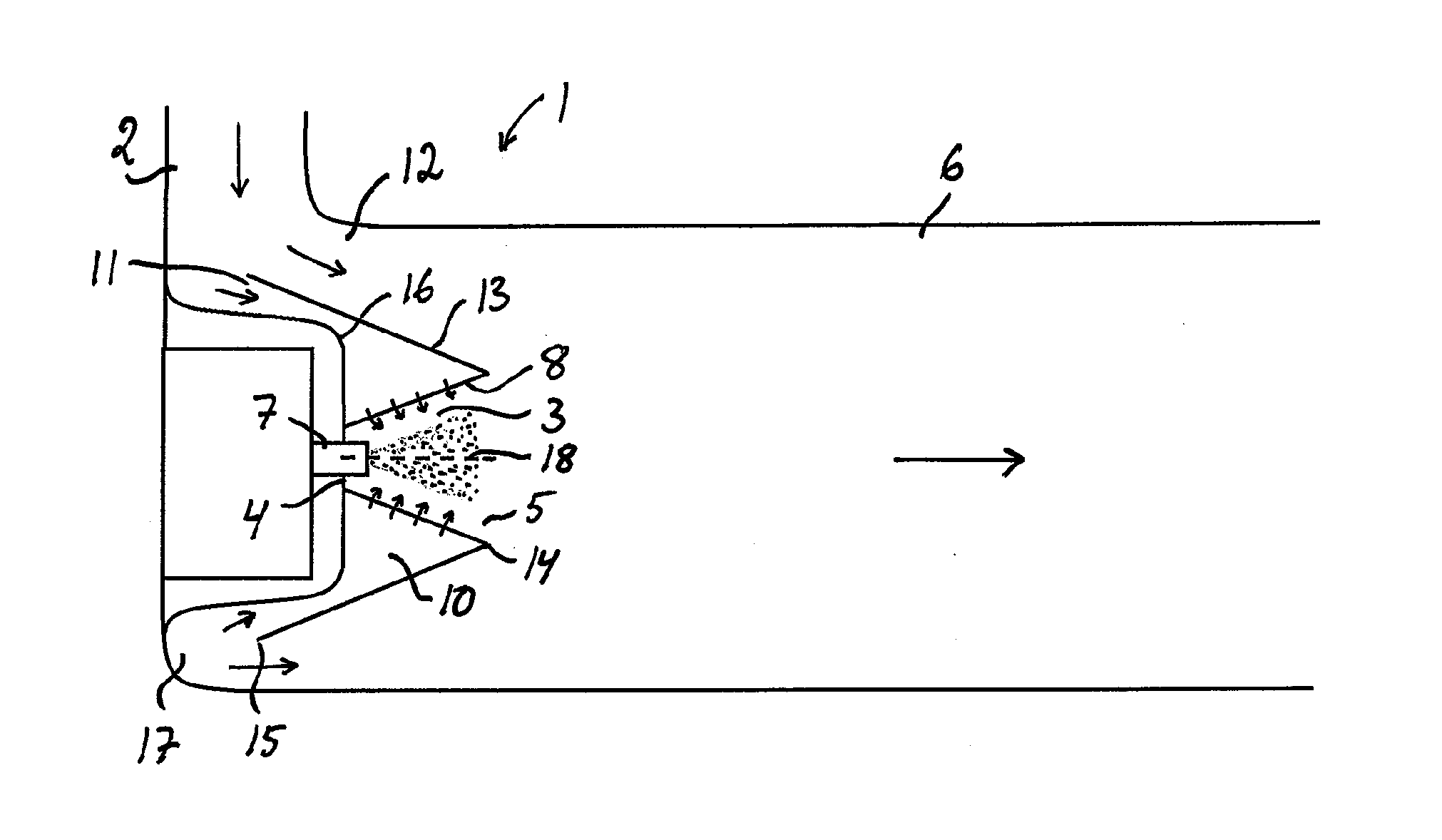
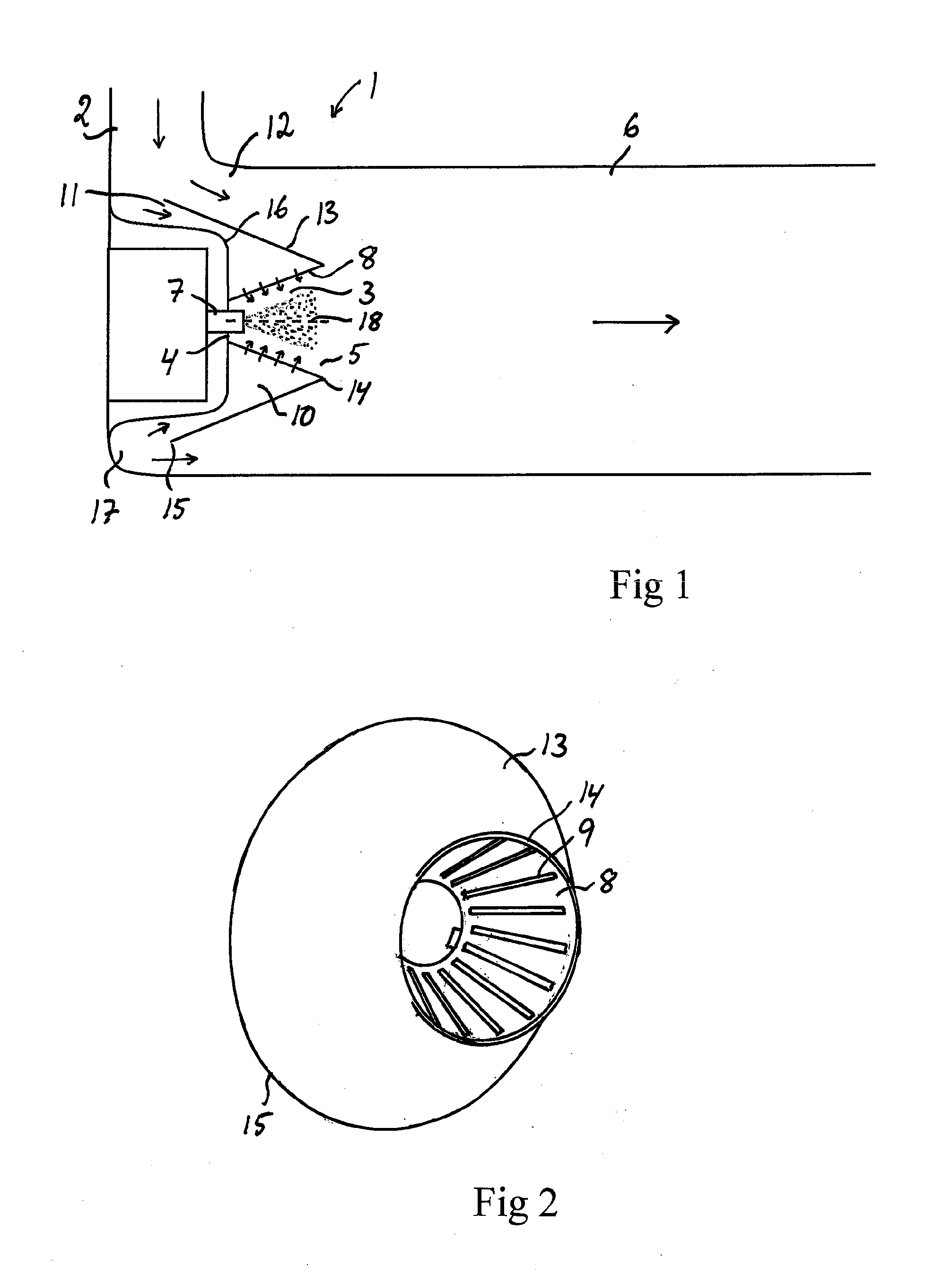
[0025]FIG. 1 illustrates an arrangement 1 according to the present invention for introducing a liquid medium into exhaust gases from a combustion engine. The arrangement may for example be situated in an exhaust line upstream of an SCR catalyst in order to introduce a liquid reducing agent in the form of urea or ammonia into the exhaust line upstream of the SCR catalyst, or be situated in an exhaust post-treatment device in order to introduce a liquid reducing agent in the form of urea or ammonia upstream of an SCR catalyst which forms part of the exhaust post-treatment device.

[0026]The arrangement 1 comprises a line 2 intended to receive exhaust gases from a combustion engine and to lead them towards an exhaust post-treatment unit, e.g. in the form of an SCR catalyst. The arrangement 1 further comprises an injection chamber 3 with a closed rear end 4 and an open forward end 5. The injection chamber 3 is connected via its open forward end 5 to a mixing duct 6 which forms part of the...


PUM

PropertyMeasurementUnit
Fractionaaaaaaaaaa
Fractionaaaaaaaaaa
Pressureaaaaaaaaaa

Abstract

Arrangement for introducing a liquid medium into exhaust gases from a combustion engine: an injector for injecting the liquid medium into an injection chamber (3), a casing (8) which surrounds the injection chamber, a mixing duct (6), a gathering chamber (10) which surrounds the casing and is connected to the injection chamber via throughflow apertures of the casing, and a bypass duct (12) for leading exhaust gases into the mixing duct without passing through the gathering chamber and the injection chamber. The inlet (11) of the gathering chamber diverts a portion of the exhaust gases to flow into the gathering chamber, and then into the injection chamber via the throughflow apertures, and thereafter into the mixing duct, while the bypass duct leads another portion of the exhaust gases into the mixing duct in order to be mixed there with the diverted exhaust gases.

Description

FIELD OF THE INVENTION, AND PRIOR ART[0001]The present invention relates to an arrangement according to the preamble of claim 1 for introducing a liquid medium, e.g. urea, into exhaust gases from a combustion engine[0002]To meet prevailing exhaust cleaning requirements, today's motor vehicles are usually provided with a catalyst in the exhaust line to effect catalytic conversion of environmentally hazardous constituents of the exhaust gases to environmentally less hazardous substances. A method which has been employed for achieving effective catalytic conversion is based on injecting a reducing agent into the exhaust gases upstream of the catalyst. A reductive substance which forms part of, or is formed by, the reducing agent is carried by the exhaust gases into the catalyst and is adsorbed on active seats in the catalyst, resulting in accumulation of the reductive substance in the catalyst. The accumulated reductive substance may then react with and thereby convert an exhaust subst...

Claims


Application Information

Patent Timeline
20 Jun 2013
Publication
US20130152558A1
IPC
F01N3/10
CPC
B01F5/045; B01F3/04049; F01N3/2066; F01N2240/20; F01N2610/02; F01N2240/02; F01N2610/1453; F01N3/10
Inventors
LOMAN, PETER