
High energy blasting

a high-energy, blasting technology, applied in the direction of blasting cartridges, weapons, weapon components, etc., can solve the problems of reducing the ore-to-waste ratio, increasing the mill throughput, and causing the explosion to occur in both waste and recoverable minerals, so as to reduce the vibration of the blasting and limit the collateral damage

Active Publication Date: 2013-06-20
ORICA INT PTE LTD
View PDF15 Cites 16 Cited by
  • Summary
  • Abstract
  • Description
  • Claims
  • Application Information

AI Technical Summary

Benefits of technology

The patent describes a way to increase the energy concentration in a blasting operation while safely containing the explosives energy. This can improve rock fragmentation and increase mining efficiency. The method involves initiating a high energy layer at least 500 milliseconds after the closest explosive charge, and using buffer zones with lower powder factors to limit collateral damage and blast vibrations. The blasts can also be "drop cuts" or buffered by material from previous blasts to have no exposed free faces near the high energy zones. Overall, this patent provides a way to achieve safer, more efficient blasting.

Problems solved by technology

In some cases, blasts may occur in both waste and recoverable mineral.
It has been proposed that more dramatic increases, of the order of a factor of 2-10, may actually result in explosives energy performing much of the comminution process and lead to much larger increases in mill throughput.
If waste rock is broken into the stope then the ore-to-waste ratio decreases; a deleterious process known as dilution.
Also excessive damage to surrounding rock may lead to mine instability.
Where blast designers have strived to maximize explosive energy within the blast to achieve improved fragmentation, the blast designs have generally been limited to the highest powder factors that avoid flyrock and other damaging environmental incidents.

Method used


Image

  • High energy blasting
  • High energy blasting
  • High energy blasting

Examples


example 1

Use of Conventional Blast Methods in Open Cut Mining

[0071]This example illustrates generally conventional blasting practice and demonstrates that high powder factors using such conventional methods are not safe and hence not viable for mining operations for recoverable mineral.

example 1a

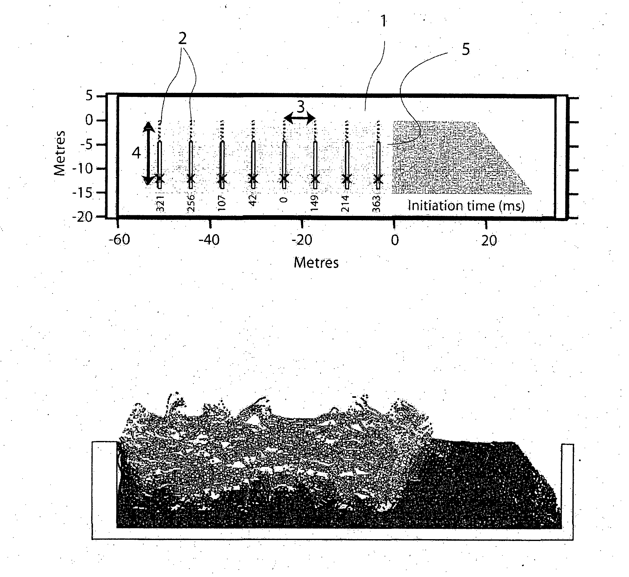
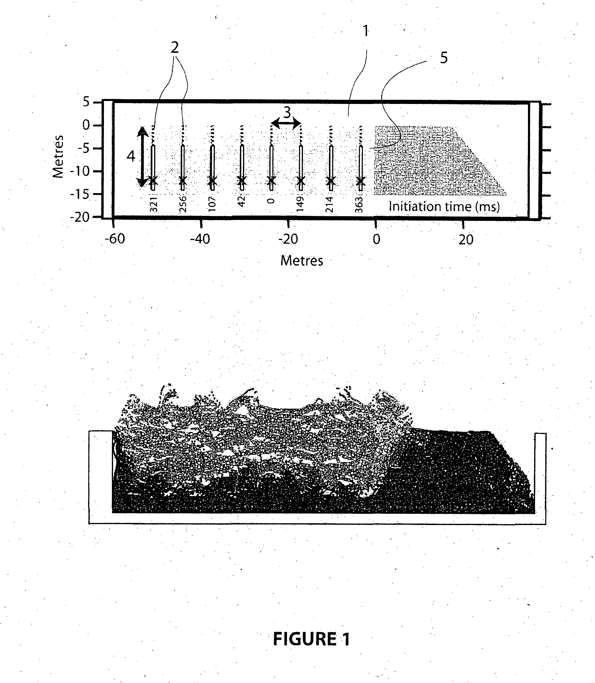
[0072]The first base case conventional blast reflects standard practice using a conventional powder factor of about 0.8 kg / m3 of unblasted rock. Referring to the cross section of the blast zone (1) shown in FIG. 1, which illustrates the vertical and horizontal depth of the blast in metres, the blast comprises eight rows (2) of thirty blastholes per row each with a nominal diameter of 229 mm. The average or nominal burdens (3) and spacings (out of the plane of FIG. 1) are 6.8 m and 7.8 m respectively. The total blasthole depths (4) are around 14 m, using 2 m of subdrill below the design bench floor depth of 12 m from the surface. All holes are loaded with a 9.4 m column of explosive thus resulting in a powder factor of about 0.8 kg explosive / m3 of unblasted rock. A body of buffer material comprising previously blasted rock is shown in a darker shade of grey, extending from the face of the blast (at 0 m). Also shown in the top part of FIG. 1 are the nominal initiation (inter-row delay...

example 1b

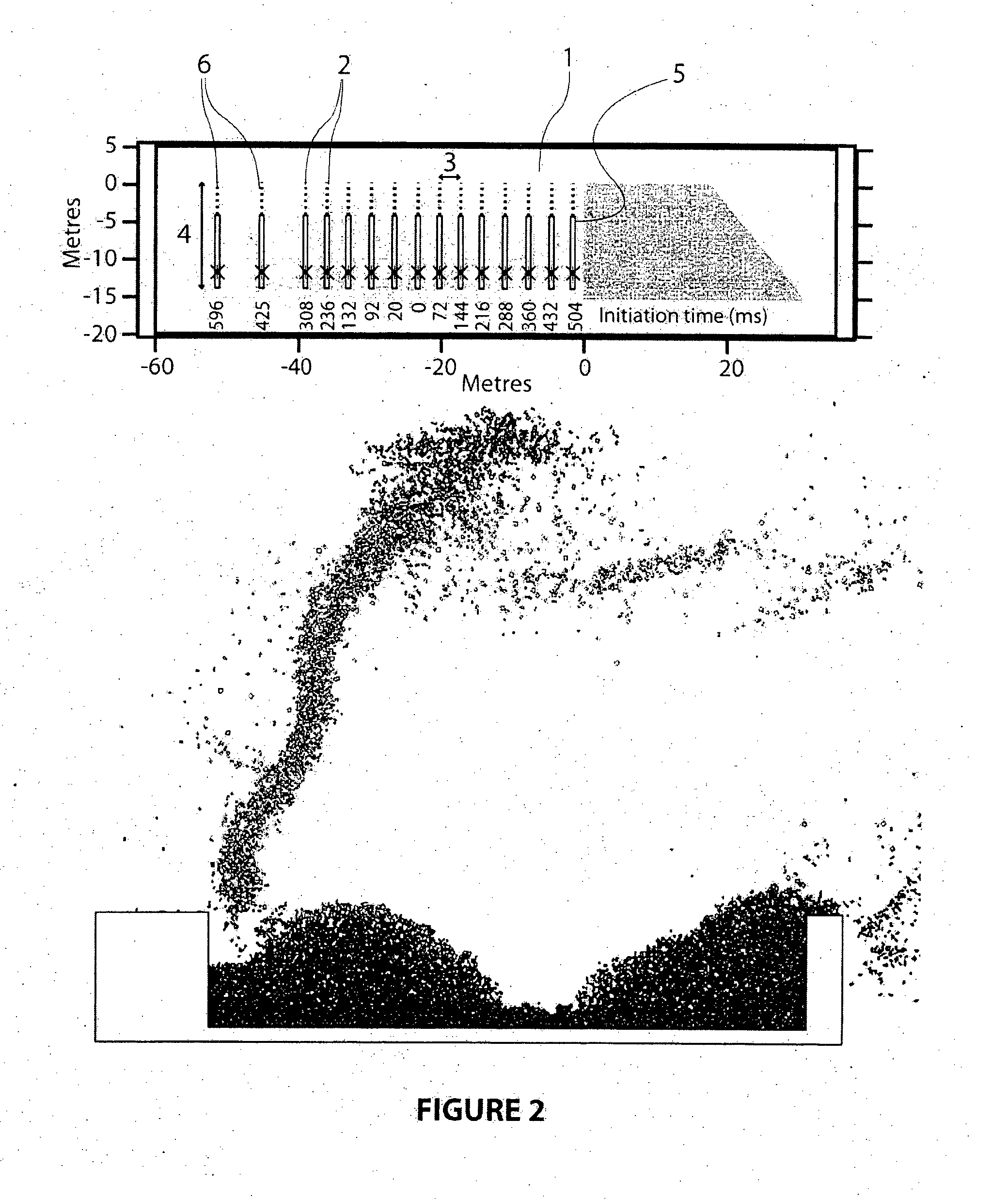
[0074]The second base case conventional blast reflects standard practice but using a very high powder factor of close to 4 kg / m3 of unblasted rock. Referring to the cross section of the blast field (1) shown in FIG. 2, which illustrates the vertical and horizontal, depth of the blast in metres, this blast comprises fifteen rows (2) of thirty blastholes pet row each with a nominal diameter of 229 min. Within this blast is a high energy zone comprising rows 1-13 (rows numbered from right to left in FIG. 2). The average or nominal burdens (3) and spacings (out of plane of the Figure) in this zone are 3.1 m and 3.1 m respectively.

[0075]The total blasthole depths (4) are around 13 m, using 1 m of subdrill below the design bench depth of 12 m from the surface. All holes are loaded with a 8.4 m column of explosive (5) thus resulting in a powder factor of about 4 kg explosive / m3 of unblasted rock. A body of buffer material comprising previously blasted rock is shown in a darker shade of gre...


PUM

PropertyMeasurementUnit
thicknessaaaaaaaaaa
depthaaaaaaaaaa
densityaaaaaaaaaa

Abstract

A method of blasting rock, in mining for recoverable material, comprising drilling blastholes in a blast zone loading the blastholes with explosives and then firing the explosives in the blastholes in a single cycle of drilling, loading and blasting. The blast zone comprises a high energy blast zone in which blastholes are partially loaded with a first explosive to provide a high energy layer of the high energy blast zone having a powder factor of at least 1.75 kg of explosive per cubic metre of unblasted rock in the high energy layer and in which at least some of those blastholes are also loaded with a second explosive to provide a low energy layer of the high energy blast zone between the high energy layer and the adjacent end of those blastholes, said low energy layer having a powder factor that is at least a factor of two lower than the powder factor of said high energy layer. The high energy blasting method provides improved rock fragmentation through increased explosive energy concentration while simultaneously alleviating deleterious environment blast effects.

Description

TECHNICAL FIELD[0001]The present invention relates to a method of blasting, and is particularly concerned with high energy blasting for recoverable mineral.BACKGROUND ART[0002]In mining for recoverable minerals, blasting provides the first step in breaking and dislodging the host rock from its initial state in the ground. This is the case whether the mining is conducted largely as a surface, or open-cut operation, or largely as a subsurface, or underground, mining operation. Blasting for recoverable minerals may occur either in rock that largely comprises waste or overburden material or in rock comprising ore or other recoverable mineral which represents recoverable concentrations of the valuable mineral or minerals to be mined. In some cases, blasts may occur in both waste and recoverable mineral.[0003]Mine productivity can be improved through blasting which achieves more effective breakage and / or movement of the rock. This may improve the efficiency of mining equipment such as exc...

Claims


Application Information

Patent Timeline
Patent Type & Authority Applications(United States)
IPC IPC(8): F42D3/04
CPCF42D3/04F42D1/055F42D1/08
Inventor BRENT, GEOFFREY FREDERICKGOSWAMI, TAPANNOY, MICHAEL JOHNDARE-BRYAN, PETER
Owner ORICA INT PTE LTD
Learn More