High energy blasting
a high-energy, blasting technology, applied in the direction of blasting cartridges, weapons, weapon components, etc., can solve the problems of reducing the ore-to-waste ratio, increasing the mill throughput, and causing the explosion to occur in both waste and recoverable minerals, so as to reduce the vibration of the blasting and limit the collateral damage
- Summary
- Abstract
- Description
- Claims
- Application Information
AI Technical Summary
Benefits of technology
Problems solved by technology
Method used
Image
Examples
example 1
Use of Conventional Blast Methods in Open Cut Mining
[0072]This example illustrates generally conventional blasting practice and demonstrates that high powder factors using such conventional methods are not safe and hence not viable for mining operations for recoverable mineral.
example 1a
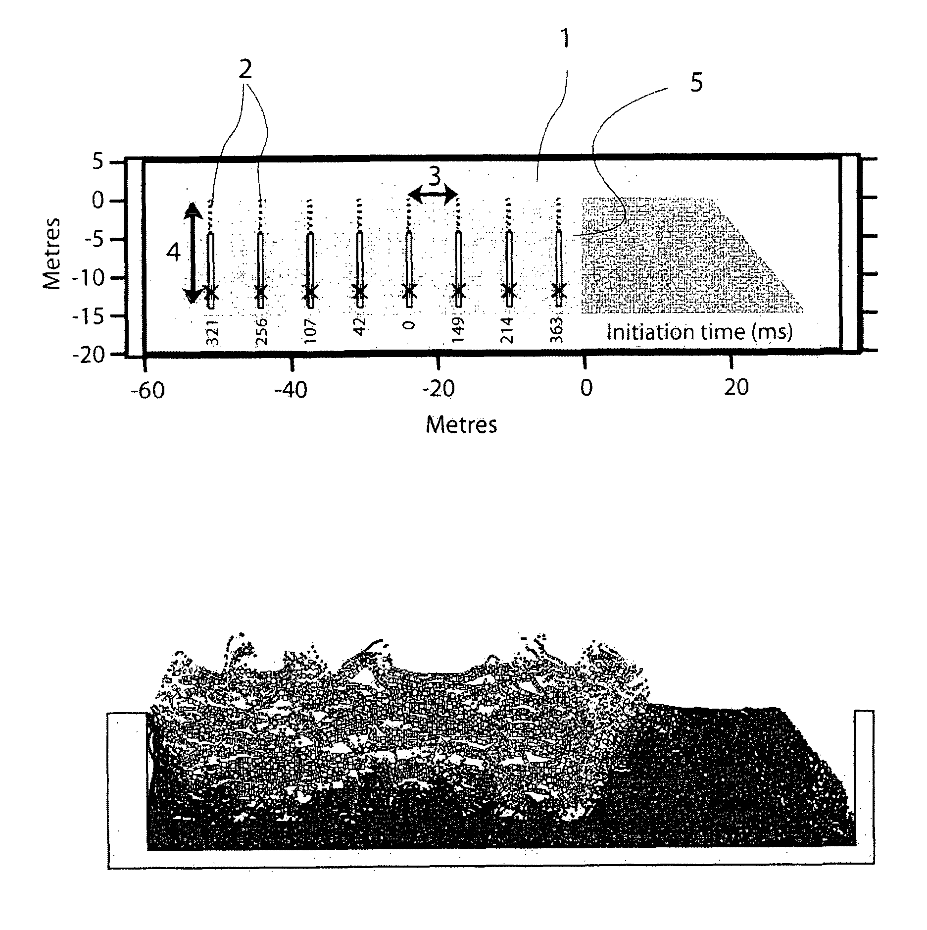
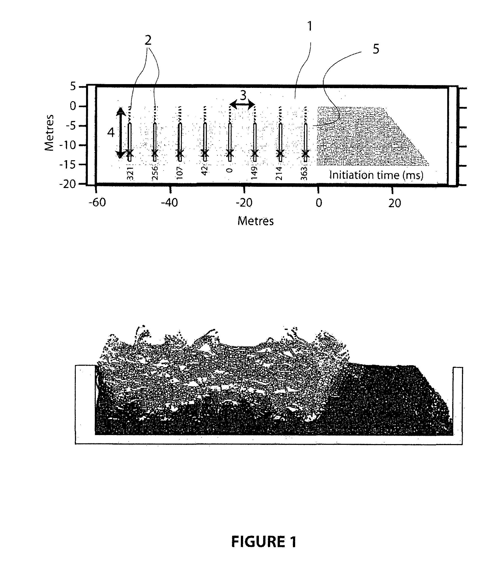
[0073]The first base case conventional blast reflects standard practice using a conventional powder factor of about 0.8 kg / m3 of unblasted rock. Referring to the cross section of the blast zone (1) shown in FIG. 1, which illustrates the vertical and horizontal depth of the blast in meters, the blast comprises eight rows (2) of thirty blastholes per row each with a nominal diameter of 229 mm. The average or nominal burdens (3) and spacings (out of the plane of FIG. 1) are 6.8 m and 7.8 m respectively. The total blasthole depths (4) are around 14 m, using 2 m of subdrill below the design bench floor depth of 12 m from the surface. All holes are loaded with a 9.4 m column of explosive thus resulting in a powder factor of about 0.8 kg explosive / m3 of unblasted rock. A body of buffer material comprising previously blasted rock is shown in a darker shade of grey, extending from the face of the blast (at 0 m). Also shown in the top part of FIG. 1 are the nominal initiation (inter-row delay...
example 1b
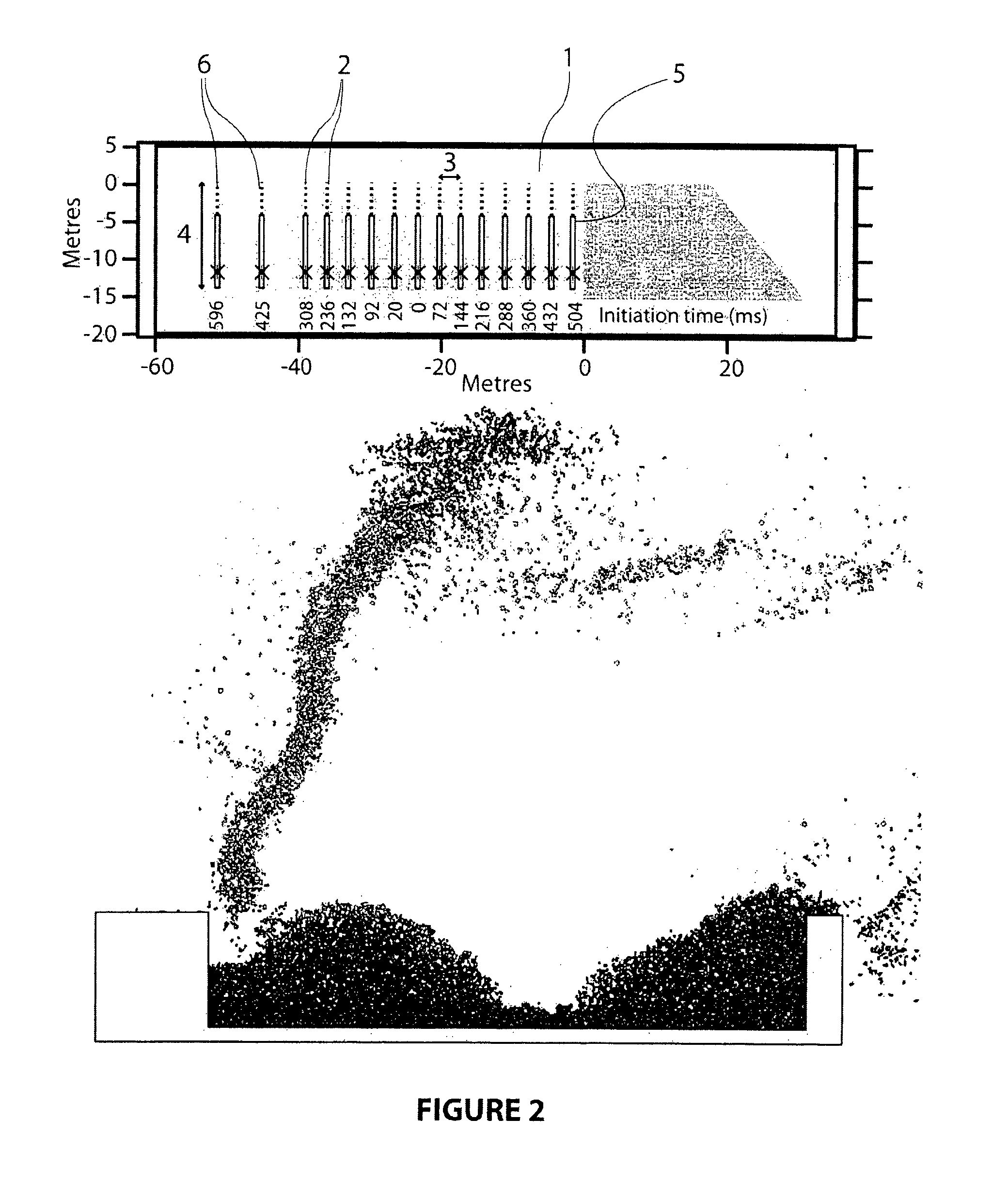
[0075]The second base case conventional blast reflects standard practice but using a very high powder factor of close to 4 kg / m3 of unblasted rock. Referring to the cross section of the blast field (1) shown in FIG. 2, which illustrates the vertical and horizontal depth of the blast in meters, this blast comprises fifteen rows (2) of thirty blastholes pet row each with a nominal diameter of 229 mm. Within this blast is a high energy zone comprising rows 1-13 (rows numbered from right to left in FIG. 2). The average or nominal burdens (3) and spacings (out of plane of the Figure) in this zone are 3.1 m and 3.1 m respectively.
[0076]The total blasthole depths (4) are around 13 m, using 1 m of subdrill below the design bench depth of 12 m from the surface. All holes are loaded with a 8.4 m column of explosive (5) thus resulting in a powder factor of about 4 kg explosive / m3 of unblasted rock. A body of buffer material comprising previously blasted rock is shown in a darker shade of grey,...
PUM
| Property | Measurement | Unit |
|---|---|---|
| thickness | aaaaa | aaaaa |
| depth | aaaaa | aaaaa |
| density | aaaaa | aaaaa |
Abstract
Description
Claims
Application Information
 - R&D
- Intellectual Property
- Life Sciences
- Materials
- Tech Scout
- Unparalleled Data Quality
- Higher Quality Content
- 60% Fewer Hallucinations
Browse by: Latest US Patents, China's latest patents, Technical Efficacy Thesaurus, Application Domain, Technology Topic, Popular Technical Reports.
© 2025 PatSnap. All rights reserved.Legal|Privacy policy|Modern Slavery Act Transparency Statement|Sitemap|About US| Contact US: help@patsnap.com


