Solar Cell Combination

a solar cell and combination technology, applied in photovoltaic energy generation, photovoltaics, electrical equipment, etc., can solve the problems of increased line resistance of contact structures, further shading on the front side surface, and reducing efficiency, so as to achieve the effect of improving efficiency and minimizing costs

Inactive Publication Date: 2013-06-20
SOLARWORLD INNOVATIONS
View PDF2 Cites 12 Cited by
  • Summary
  • Abstract
  • Description
  • Claims
  • Application Information

AI Technical Summary

Benefits of technology

[0019]It is an object of the invention to provide a solar cell combination, wherein costs are minimized and the efficiency of the solar cells is improved.

Problems solved by technology

A larger width causes a decrease of efficiency due to the resulting increased shading, whereas reducing the width results in the disadvantage that the line resistance of the contact structure is increased.
Furthermore, the current of the individual contact structures is fed into busbars causing further shading on the front side surface.
The result of this is that there is a loss on the front side caused by the shading.
A problem here is the handling and positioning of the thin wires on the solar cell.
In particular the series connection of the cells causes problems since—analogous to the solder ribbons of the standard soldering process—the wires have to be brought from the front side of the first solar cell to the back side of the second solar cell.
The disadvantage of this solution is that only connectors in the form of strips can be used which, moreover, have to be turned over.
Overall, structuring and connecting individual solar cells by using perforated strip conductors is problematic, and using edge insulations involves increased manufacturing-related expenses.
Producing the mesh-like wire conductor is relatively complicated.
A significant disadvantage of this solution is also that the efficiency is negatively influenced because the areas for contacting between front side and back side are required in two dimensions.
The strings produced as a pre-stage for the assembly of modules have the disadvantage that the cells are put on individually and are covered with tin-plated copper band pieces which cover the cells and also extend below the next cell to be put on.
The required connections are produced successively in individual process steps resulting in long production times.
Due to the use of the film and the adhesive, this constructional configuration is very complicated.
In the case of an irregular thickness of the adhesive layer, the wires protrude irregularly from said adhesive layer or can also be completely covered by the adhesive, which can result in defects.
Furthermore, the film and the adhesive remain in the module; this implies relatively high demands in terms of long-term stability to be met by the adhesive and the film and therefore causes relatively high costs.
Moreover, the prefabrication of electrodes from wire, optically transparent film and adhesive is technologically sophisticated.
In the case of this solution, handling is relatively complicated.
This embodiment is very complicated and it can easily occur that the thin bent wire gets crushed.
Furthermore, all known assembly technologies for solar modules have reached their limits with regard to their possible cycle time and the processing of thin cell materials, which is counteracted through stringing together a plurality of machines.
In general, this has a negative effect on the production costs.
Moreover, the connection materials cover an undesirably large portion of the usable silicon surface and thus deteriorate the efficiency of the solar cell.
This makes the solar cells even more expensive.

Method used


Image

  • Solar Cell Combination
  • Solar Cell Combination
  • Solar Cell Combination

Examples


Embodiment Construction

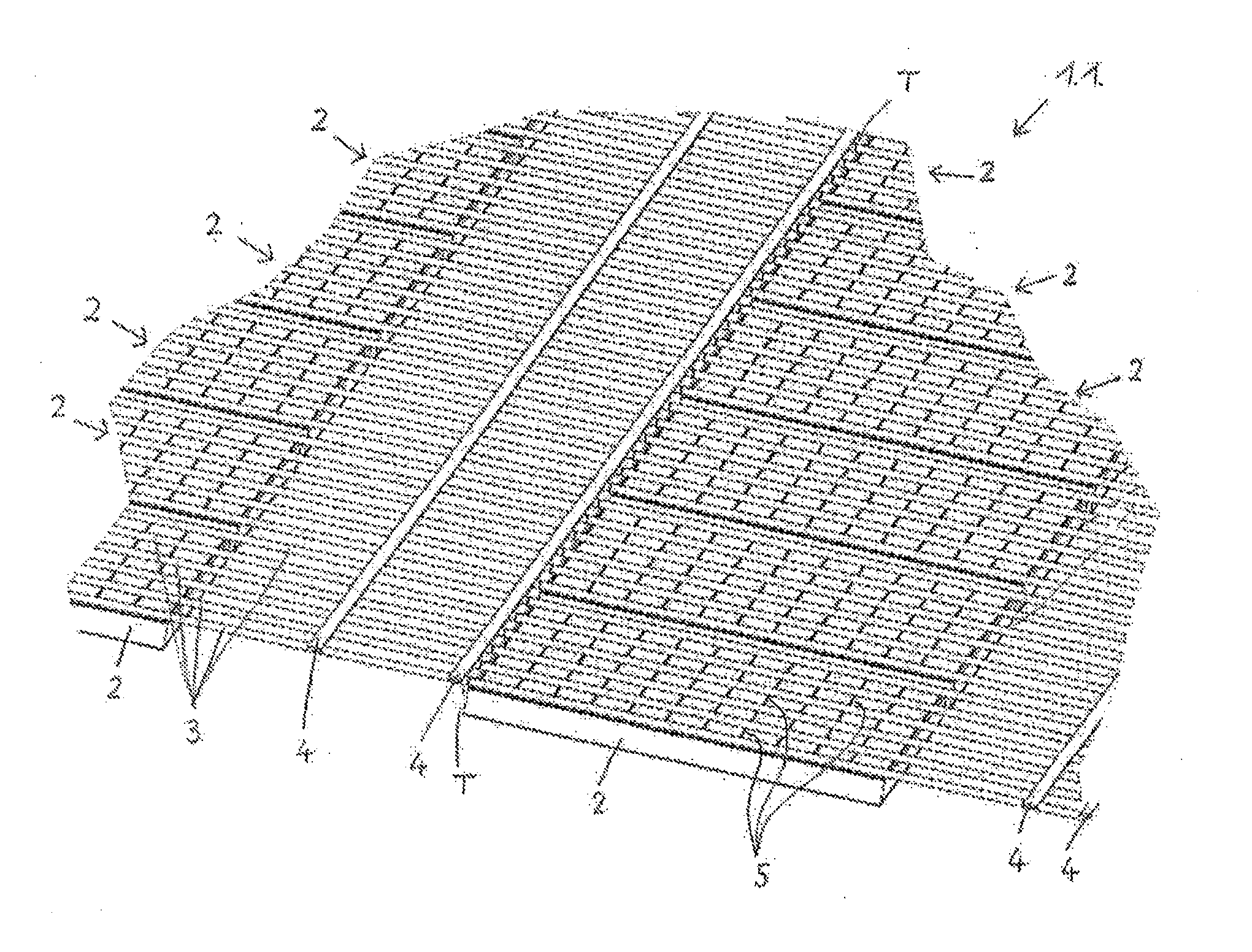
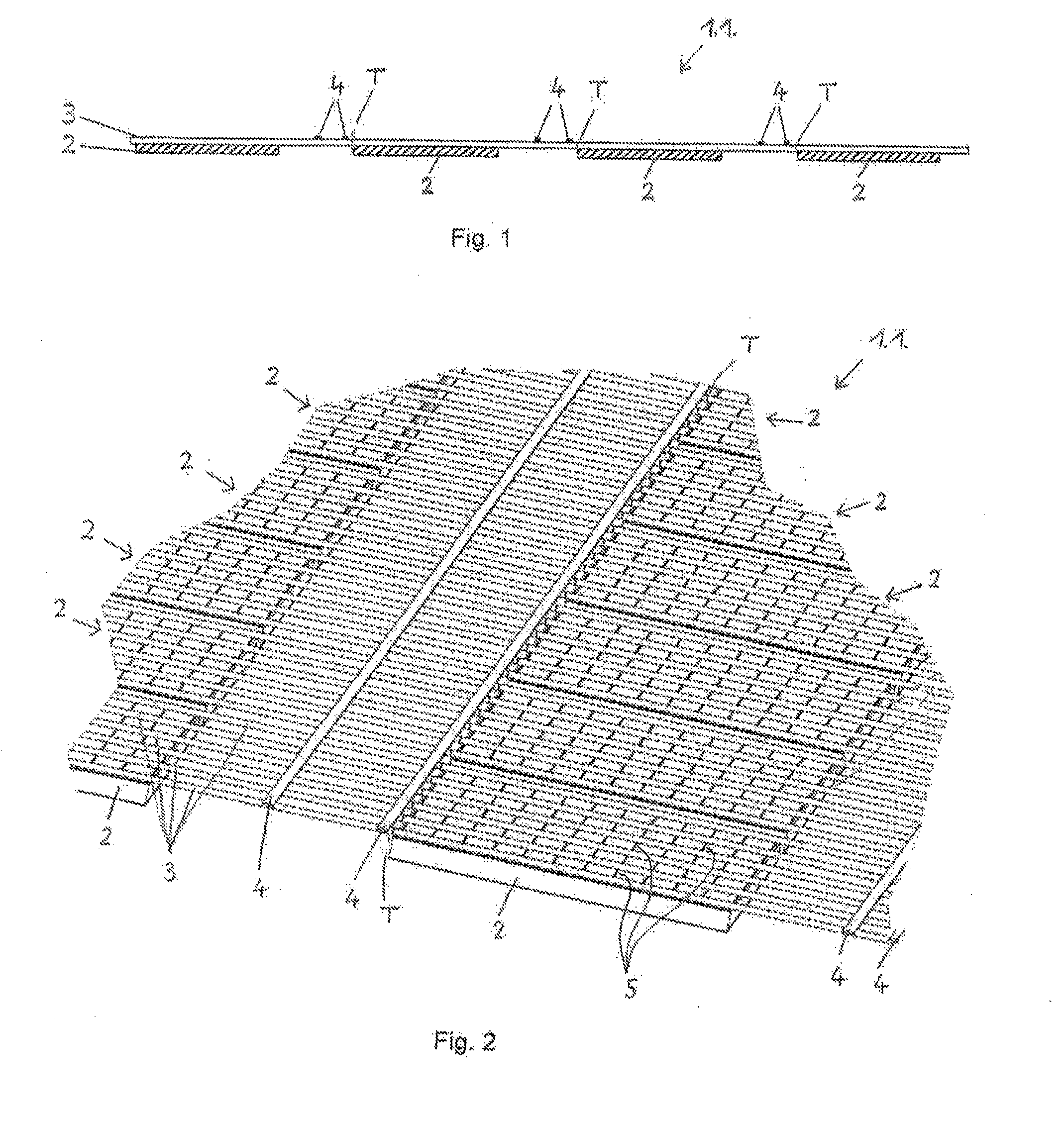
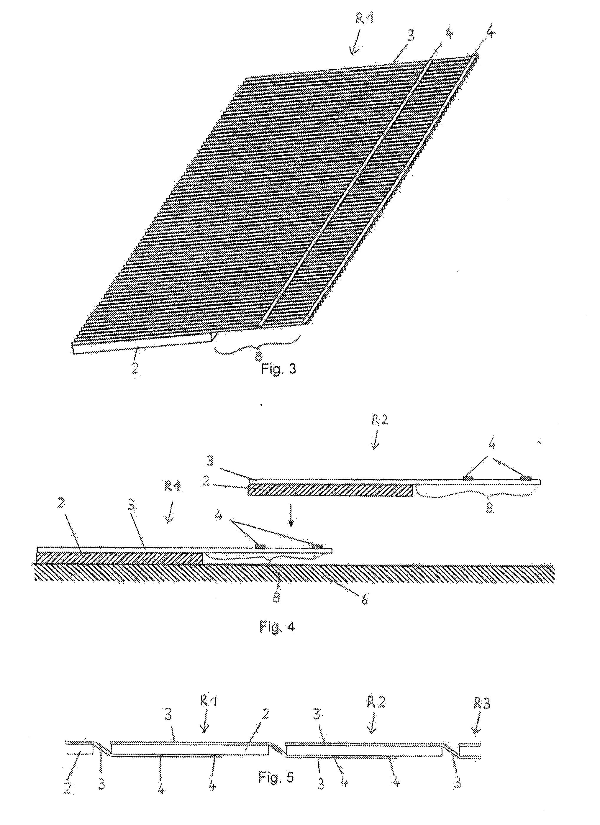
[0103]FIGS. 1 to 6 illustrate the method steps for producing the first variant of a solar cell combination 1 from solar cells 2 by using first wire conductors 3 and further contact elements in the form of cross-connectors 4 running transverse to said first wire conductors.

[0104]FIGS. 1 and 2 illustrate a first production step wherein a multiplicity of solar cells 2 were placed next to each other and one behind the other onto a non-illustrated support. A multiplicity of first continuous wire conductors 3 were positioned over the solar cells 2 in the longitudinal direction, and cross-conductors 4 were placed transverse to and above the first wire conductors 3 and in each case between a row of successively arranged solar cells 2 and also spaced apart from the successively arranged solar cells.

[0105]In the FIGS. 1 and 2, a separating line T is indicated in each case directly before a solar cell 2. FIG. 2 shows that on the surface of the solar cells 2, strip conductors 5 are printed tran...


PUM


Abstract

A solar cell combination having at least two independent electrodes, in which at least one first electrode is formed by at least one first wire conductor that first spans a plurality of solar cells, and in which the first and the second electrodes are contacted with each other, and the first and / or second electrode is disconnected at the positions required for the connection.

Description

BACKGROUND OF THE INVENTION[0001]The invention relates to a solar cell combination, wherein contacting the solar cells is carried out through wire conductors, and a plurality of solar cells are combined with each other through the wire conductors so as to form the solar cell combination.[0002]A solar cell usually consists of a substrate having a front side and a back side, wherein a contact structure is applied onto at least one of the two sides. Typically, the contact structure has a width of at least 100 μm, whereas its thickness is only approximately 10 to 15 μm. A larger width causes a decrease of efficiency due to the resulting increased shading, whereas reducing the width results in the disadvantage that the line resistance of the contact structure is increased. Furthermore, the current of the individual contact structures is fed into busbars causing further shading on the front side surface.[0003]On the back side of the solar cell there is usually a large-area contact structu...

Claims


Application Information

Patent Timeline
Patent Type & Authority Applications(United States)
IPC IPC(8): H01L31/05
CPCY02E10/50H01L31/18H01L31/0508H01L31/05
Inventor SCHAARSCHMIDT, MATTHIASRICHTER, THILOENGER, WOLFGANGSEIDEL, THOMASGRUNOW, PAULKUTZER, MARTINSTORBECK, OLAFNEUHAUS, HOLGERGEORGI, MATTHIAS
Owner SOLARWORLD INNOVATIONS
Why Eureka
Try Eureka