Automatic chemical treatment system with liquid level sensor in chemical tank for calibration and chemical dispensing rate control

a technology of automatic chemical treatment system and liquid level sensor, which is applied in the direction of level control, instrumentation, and wellbore/well accessories, etc., can solve the problems of insufficient or excessive amount of chemical, and relatively high flow ra

Active Publication Date: 2013-06-20
PRO JECT CHEM LLC
View PDF3 Cites 12 Cited by
  • Summary
  • Abstract
  • Description
  • Claims
  • Application Information

AI Technical Summary

Problems solved by technology

It has been observed that accuracy of such devices when dealing with small total volumes, yet at relatively high flow rates may be inadequate.
Thus, the amount of chemical may be insufficient or excessive for any particular well, and it is typically necessary for a human operator to observe the indicator to determine when it is necessary to refill the storage tank with chemical.

Method used


Image

  • Automatic chemical treatment system with liquid level sensor in chemical tank for calibration and chemical dispensing rate control
  • Automatic chemical treatment system with liquid level sensor in chemical tank for calibration and chemical dispensing rate control
  • Automatic chemical treatment system with liquid level sensor in chemical tank for calibration and chemical dispensing rate control

Examples


Embodiment Construction

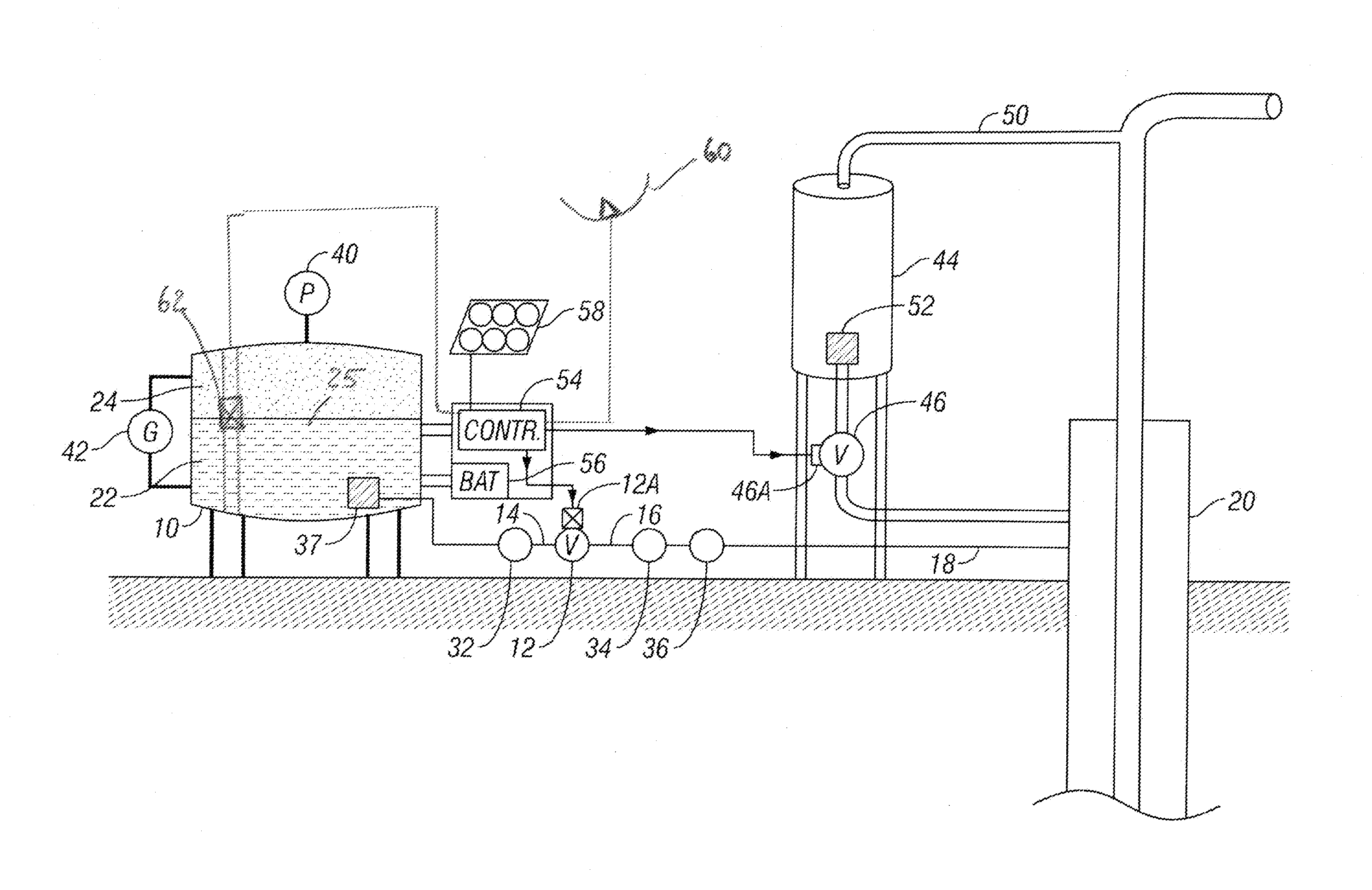
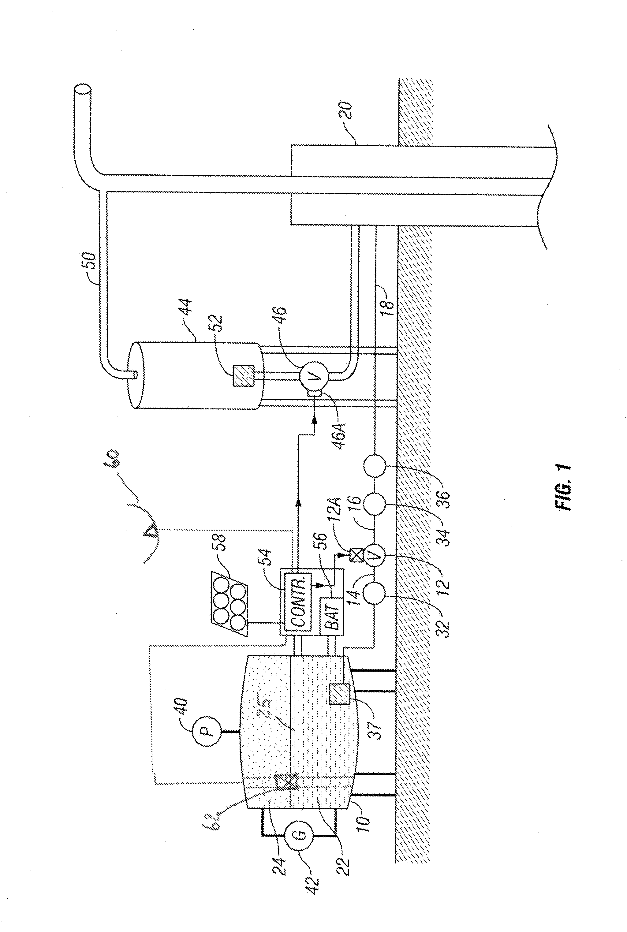
[0016]An example embodiment of a chemical treating system according to the invention is shown schematically in FIG. 1. A chemical dispenser vessel 10, substantially as described in U.S. Pat. No. 5,209,300 to Ayres, incorporated herein by reference, includes a container which is capable of holding an internal pressure without failure. The chemical dispenser vessel 10 is distinguishable from containers such as tanks which may only be designed to withstand the hydrostatic pressure exerted by fluid in the tank. Preferably, the chemical dispenser vessel 10 is made from glass, carbon fiber or composite fiber reinforced plastic, from stainless steel, or from any other material which is resistant to degradation induced by chemicals and corrosive gases. Alternatively, the chemical dispenser vessel 10 can include an inner lining (not shown) resistant to chemical degradation. A first control valve 12, which in the present embodiment may be actuated by an electrically operated actuator 12A, for...


PUM


Abstract

A wellbore chemical treating system include a storage vessel for containing a treating chemical. A chemical dispenser is in fluid communication between an outlet of the vessel and a well for selectively controlling the flow of the chemical from the vessel to the well. A liquid level sensor is disposed in the storage vessel. A controller is in signal communication with the liquid level sensor and is configured to operate the chemical dispenser. The controller is configured to adjust an operating time of the chemical dispenser based on changes in a liquid level measured by the liquid level sensor over a selected period of time.

Description

CROSS-REFERENCE TO RELATED APPLICATIONS[0001]Not ApplicableSTATEMENT REGARDING FEDERALLY SPONSORED RESEARCH OR DEVELOPMENT[0002]Not applicable.BACKGROUND OF INVENTION[0003]1. Field of the Invention[0004]The invention relates generally to the field of chemical treatment systems for use with hydrocarbon producing wells. More specifically, the invention relates to chemical treatment systems which inject chemicals into the well.[0005]2. Background Art[0006]Chemical treatment systems are used in hydrocarbon producing wells to introduce various chemicals into such wells to, for example, control or prevent buildup of scale from water produced from subsurface formations, reduce or remove solid hydrocarbon deposits and to inhibit corrosion of metal components in the wellbore, among other purposes. Chemical treatment systems known in the art include chemical pumps that withdraw chemical from a storage tank and introduce the treatment chemical(s) into the wellbore.[0007]One device known in the...

Claims


Application Information

Patent Timeline
Patent Type & Authority Applications(United States)
IPC IPC(8): E21B43/16G05D9/12
CPCG05D7/0635
Inventor AYRES, ROBERT N.
Owner PRO JECT CHEM LLC
Why Eureka
Try Eureka