Sealing assembly

a technology of sealing assembly and sealing seal, which is applied in the direction of engine seals, piston rings, mechanical equipment, etc., can solve the problems of increasing the overall cost of the system, increasing the weight and space required, and often not seeing any improvement in the area away from the pumping mechanism features, so as to reduce the leakage and alter the sealing performance

Inactive Publication Date: 2013-06-20
HOOWAKI
View PDF33 Cites 13 Cited by
  • Summary
  • Abstract
  • Description
  • Claims
  • Application Information

AI Technical Summary

Benefits of technology

[0017]An advantage of the present invention is that it provides a sealing assembly suitable for bi-directional rotation or linear translation.
[0018]Another advantage of the present invention is that it allows for a tailoring of the surface structure to alter the seal performance.
[0019]Yet another advantage of the present invention is that it provides a sealing assembly that reduces the leakage using a pumping action that result from the interaction of the nano-textured surface(s).
[0020]Yet another advantage of the present invention is that the shape and distribution of the textured surface creates a pressure to separate the surfaces, with the surface structure attracting the fluids to stay with the surface, and to resist the shearing of the fluid film.

Problems solved by technology

Problems with these types of seals are that they are typically unidirectional seals for best effectiveness, the hydrodynamic pumping is dependent heavily on having relative rotation, and the effect is often limited to only a select portion of the contact surface, so areas away from the pumping mechanism features often do not see any improvement.
Reliability of the sealing system is of paramount concern, because of the cost of downtime in certain operations.
This increases the weight and space required, increasing the overall cost of the system, and does not provide the necessary sealing performance for the expected duration due to eventual pressure build-up between the two seals eventually destroying the seals.
Since almost all seals utilize the process liquid or gas to lubricate the seal faces, they are designed to leak.
However leakage is a concern particularly as the pressure against the seal may be higher as a shaft turns within the seal.

Method used


Image

  • Sealing assembly
  • Sealing assembly
  • Sealing assembly

Examples


Embodiment Construction

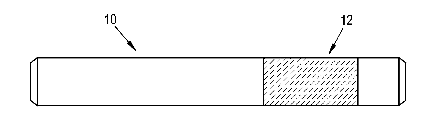
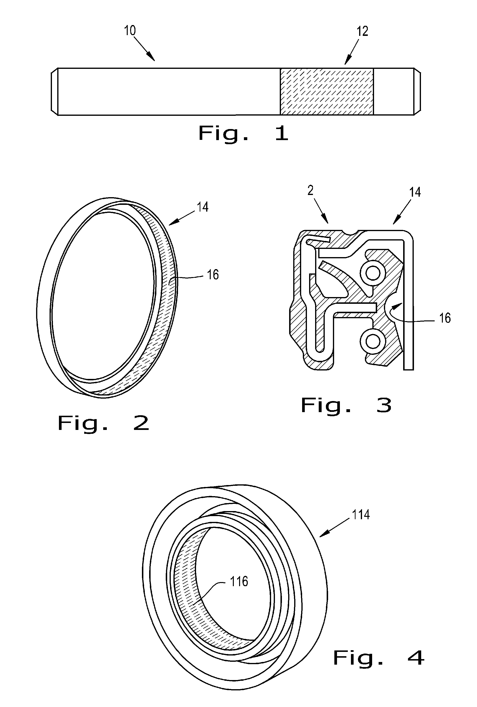
[0031]Referring now to the drawings there is shown an embodiment of a sealing assembly of the present invention with nano patterns on the surfaces of seals and bearings. Now, referring to FIG. 1 there is illustrated a cylindrical shaft or rod 10 with a surface structure 12 in the form of a nano-textured surface 12. Now, additionally referring to FIG. 2 there is illustrated a seal 14 having surface structure 16 in the form of a nano-textured surface 16, with a cross-sectional view of a seal assembly 2 shown in FIG. 3, with nano-textured surface 16 of seal 14 in contact with other portions of seal assembly 2.

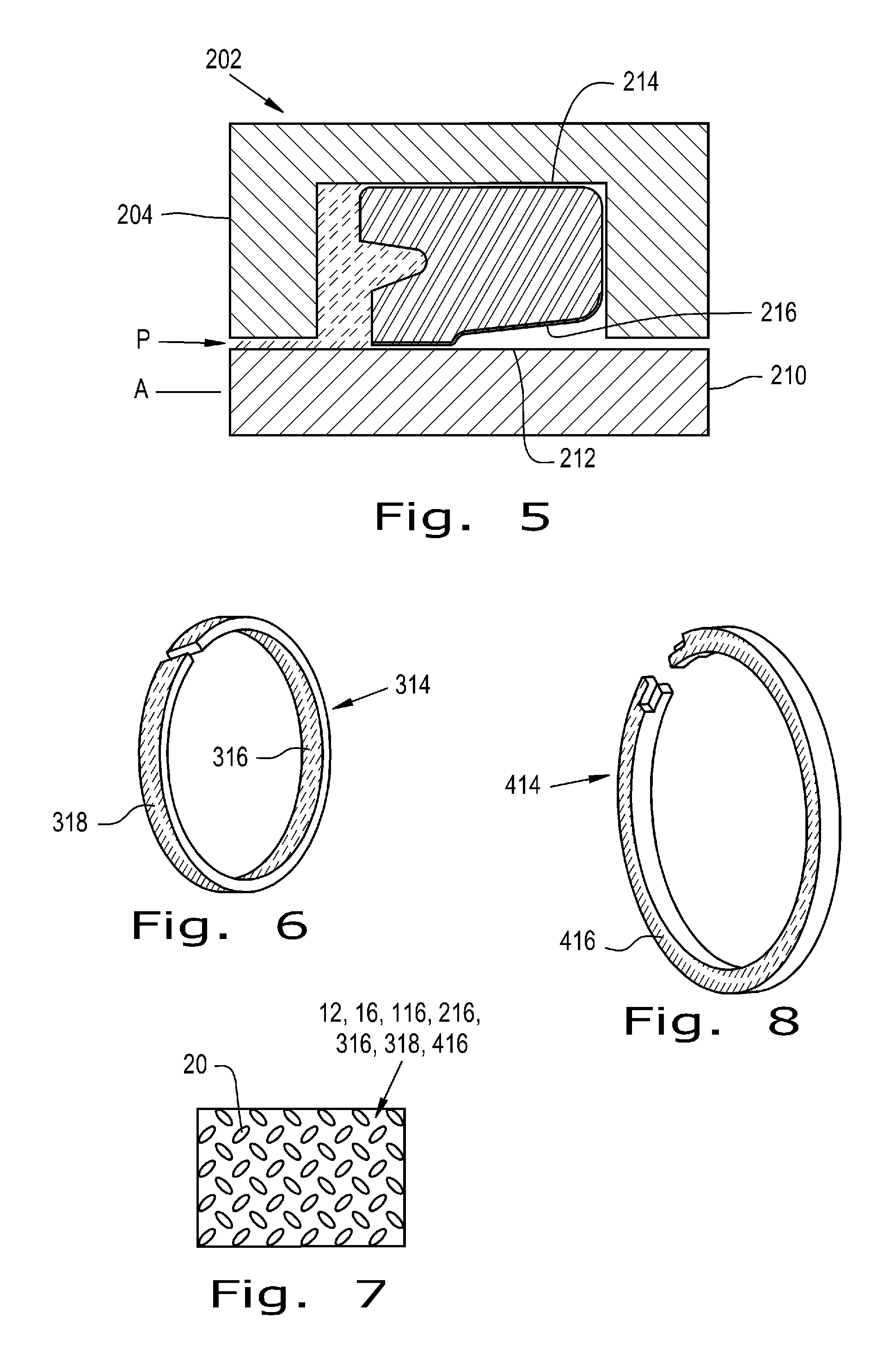
[0032]Now, additionally referring to FIG. 4 there is shown a seal 114 with a surface structure 116. The numbers used herein, with some multiple of 100 added thereto, is to denote a similarity with other parts having the same two least significant digits. Reference numbers herein relative to a specific structure or property should be broadly understood to apply to other structures ...


PUM


Abstract

A sealing assembly including a sealing component and a structural member. The sealing component has a first surface structure. The structural member has a second surface structure. A portion of the second surface structure is in contact with at least a portion of the first surface structure. The first surface structure and / or the second surface structure is a nano-textured surface. Interaction of the first surface structure with the second surface structure dynamically reduces friction, leakage of a fluid, and / or wear between the sealing component and the structural member.

Description

CROSS REFERENCE TO RELATED APPLICATIONS[0001]This is a non-provisional application based upon U.S. provisional patent application Ser. No. 61 / 576,150, entitled “SEALING AND / OR BEARING SYSTEM WITH A MICRO OR NANO PATTERN”, filed Dec. 15, 2011, which is incorporated herein by reference.BACKGROUND OF THE INVENTION[0002]1. Field of the Invention[0003]The present invention relates to sealing systems, and, more particularly, to dynamic sealing assemblies.[0004]2. Description of the Related Art[0005]A mechanical seal such as a radial shaft seal, also known as a lip seal, is used to seal rotary elements, such as a shaft rotating relative to a housing. Lip seals include strut seals, hydraulic pump seals, axle seals and power steering seals. Historically these seals may have used materials such as rawhide as the sealing element. Today a vast array of elastomers have replaced rawhide for use in sealing elements.[0006]Seal construction typically includes a sprung main sealing lip which is in co...

Claims


Application Information

Patent Timeline
Patent Type & Authority Applications(United States)
IPC IPC(8): F16J15/16
CPCF16J15/16F16J15/324F16J15/162
Inventor SITKO, MARK C.CASTLEMAN, LARRY J.MACQUEEN, COLIN D.
Owner HOOWAKI
Why Eureka
Try Eureka