Pulsed light source

a laser source and pulse technology, applied in the field of pulsed laser sources, can solve the problems of not offering the possibility of controlling the carrier envelope phase (cep) of pulses, strong technical limitation of many of the aforementioned systems, and unable to achieve the effect of a wide range of bandwidths, low amount of dispersive amplifier materials, and high single pass gain

Inactive Publication Date: 2013-06-20
FUNDACIO INST DE CIENCIES
View PDF2 Cites 3 Cited by
  • Summary
  • Abstract
  • Description
  • Claims
  • Application Information

AI Technical Summary

Benefits of technology

[0013]The first arm does not necessarily apply any modification to the pulsed signal s0 (although it may include frequency shifting, amplification stages or other signal conditioning modules), thus generating a wavelength λ0. The second arm comprises wavelength shifting means which shift the pulsed signal s0 to a second wavelength λ1. The signals resulting from the first and second arms are then frequency mixed, preferably by a Difference-Frequency Generation (DFG) Crystal, resulting in a broad bandwidth idler signal centered at a greater wavelength λ2, typically located in, but not restricted to, the mid Infra-red (mid-IR). In order to reach the energy thresholds to activate the DFG, signals from both arms are required to be broadband ultrashort pulses. Also, as the signals generated at the first and second arms come from the same oscillator, they have the advantage of having identical CEP and of perfect temporal synchronisation.
[0014]Preferably, signals from the first arm and the second arm are coupled before the frequency mixing, thus reducing the need for alignment of the system. Also preferably, the system comprises a pulse stretcher which operates on the idler output.
[0019]Advantageously, OCPCA preserves CEP, operates in a wide range of bandwidths, and by offering a very high single pass gain, allows the pulsed light source to be built in a compact system with low amounts of dispersive amplifier materials.

Problems solved by technology

These pulses are characterised by a high peak intensity, which can lead to nonlinear effects in different materials.
Additionally, these systems do not offer the possibility to control the Carrier Envelope Phase (CEP) of the pulses.
This last point in particular has been a strong technical limitation of many of the aforementioned systems.

Method used


Image

  • Pulsed light source
  • Pulsed light source

Examples


Embodiment Construction

[0023]The matters defined in this detailed description are provided to assist in a comprehensive understanding of the invention. Accordingly, those of ordinary skill in the art will recognise that variation, changes and modifications of the embodiments described herein can be made without departing from the scope and spirit of the invention. It should also be noticed that values for the wavelengths, energy and duration of optical signals are presented to facilitate the comprehension of the invention. These values are to be regarded as mere examples, as other combinations of said values can be used to generate the ultrashort pulses.

[0024]Note that in this text, the term “comprises” and its derivations (such as “comprising”, etc.) should not be understood in an excluding sense, that is, these terms should not be interpreted as excluding the possibility that what is described and defined may include further elements, steps, etc.

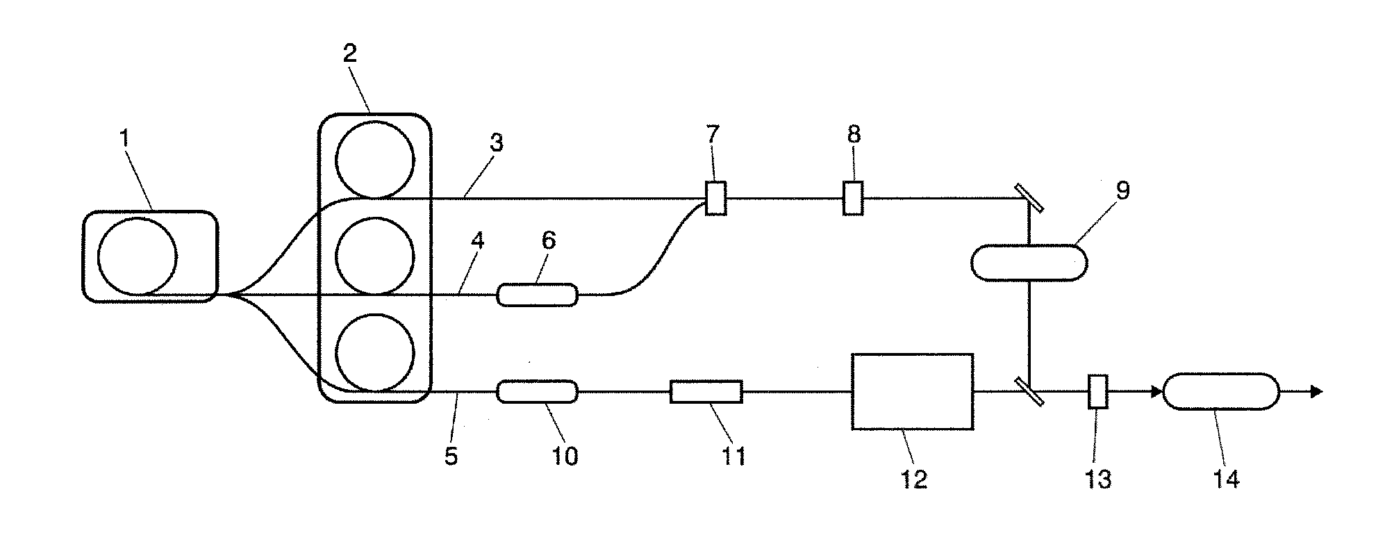
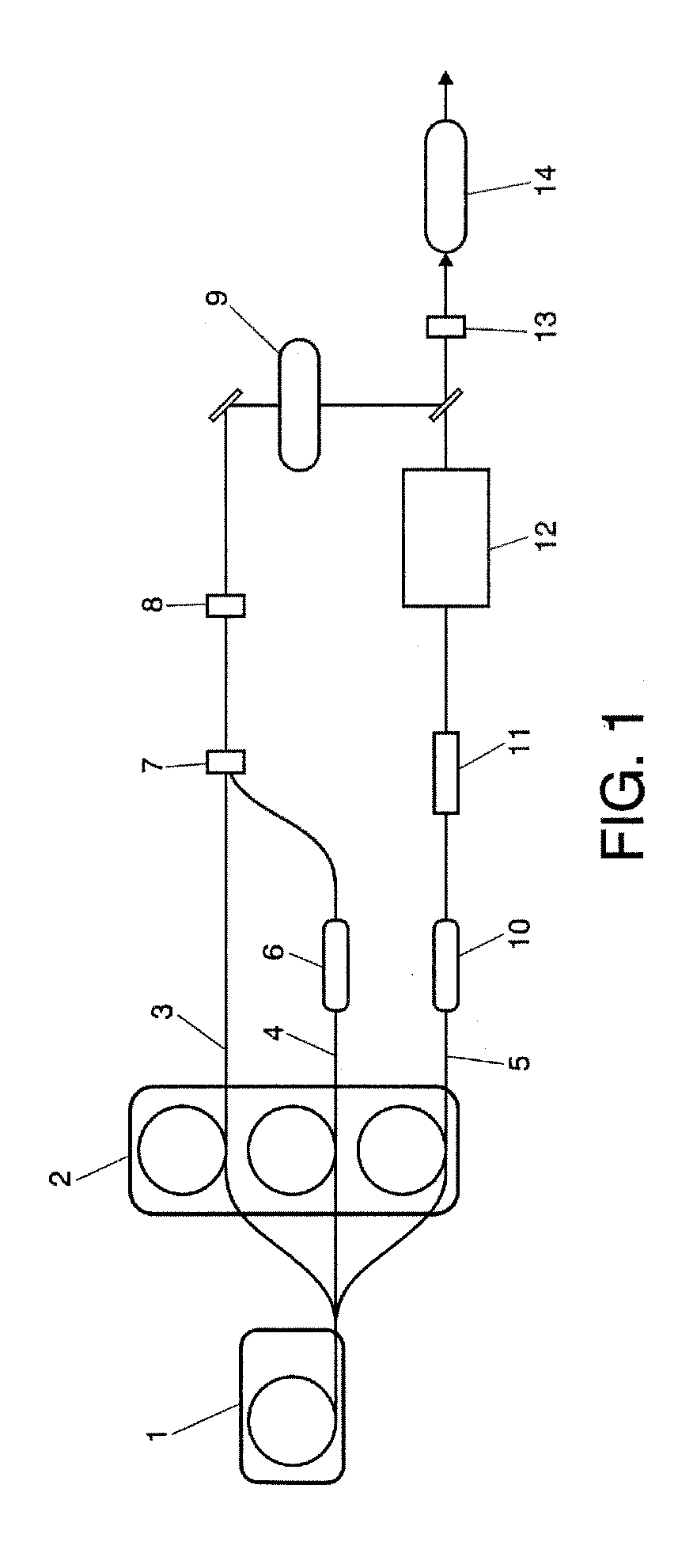
[0025]FIG. 1 presents a preferred scheme of the pulsed lig...


PUM


Abstract

Pulsed light source comprising pulse generation means (1), such as an optical oscillator, whose output is divided into three arms: two arms (3, 4) to generate a CEP-stable, ultrabroadband idler output; and a third arm (5) to generate a narrowband pump output. The pump output and idler output seed an OPCPA (13), generating stable ultrashort pulses.

Description

FIELD OF THE INVENTION[0001]The present invention has its application within the sector of light sources and especially, in the field of pulsed laser sources.BACKGROUND OF THE INVENTION[0002]The generation of ultrashort light pulses is one of the main lines of research in the field of laser sources. The term “ultrashort pulses” refers to pulses with lengths ranging from hundreds of femtoseconds to picoseconds. These pulses are characterised by a high peak intensity, which can lead to nonlinear effects in different materials. Applications of ultrashort pulses include, for example, medical imaging, Terahertz rays generation and frequency comb generation.[0003]However, it should be noted that there are significant differences between pulses of around 100 fs and pulses under about 30 fs. Because of the Fourier-transform relationship between the temporal and frequency domain descriptions of the laser pulse, the bandwidth of short pulses increases as their time duration decreases. Thus, i...

Claims


Application Information

Patent Timeline
Patent Type & Authority Applications(United States)
IPC IPC(8): H01S3/10
CPCG02F1/39H01S3/005H01S3/10H01S3/0092H01S3/2383H01S3/0057
Inventor BIEGERT, JENSCHALUS, OLIVIERBATES, PHILIP
Owner FUNDACIO INST DE CIENCIES
Why Eureka
Try Eureka