Wireless communication system with interference filtering and method of operation thereof

Inactive Publication Date: 2013-06-20
SAMSUNG ELECTRONICS CO LTD
View PDF10 Cites 25 Cited by
  • Summary
  • Abstract
  • Description
  • Claims
  • Application Information

AI Technical Summary

Benefits of technology

The present invention is about a way to manage interference in a wireless communication system. It is straightforward, cost-effective, and can be easily adapted to existing technologies. It offers compatibility with existing manufacturing processes and technologies. Overall, this invention helps reduce costs, simplify systems, and improve performance.

Problems solved by technology

The next generation cellular system, where the cell size is getting smaller so that inter-cell interference becomes a critical issue in terms of packet error performance, is in the process of deployment.
In addition, since both pico-cell and femto-cell services were recently launched, the interference signal from these local cells has also become a major source to degrade the performance for the desired signal.
None of these approaches has achieved the balance of reliable performance, speed, and implementation cost required for commercial viability.
Solutions to these problems have been long sought but prior developments have not taught or suggested any solutions and, thus, solutions to these problems have long eluded those skilled in the art.

Method used


Image

  • Wireless communication system with interference filtering and method of operation thereof
  • Wireless communication system with interference filtering and method of operation thereof
  • Wireless communication system with interference filtering and method of operation thereof

Examples


first embodiment

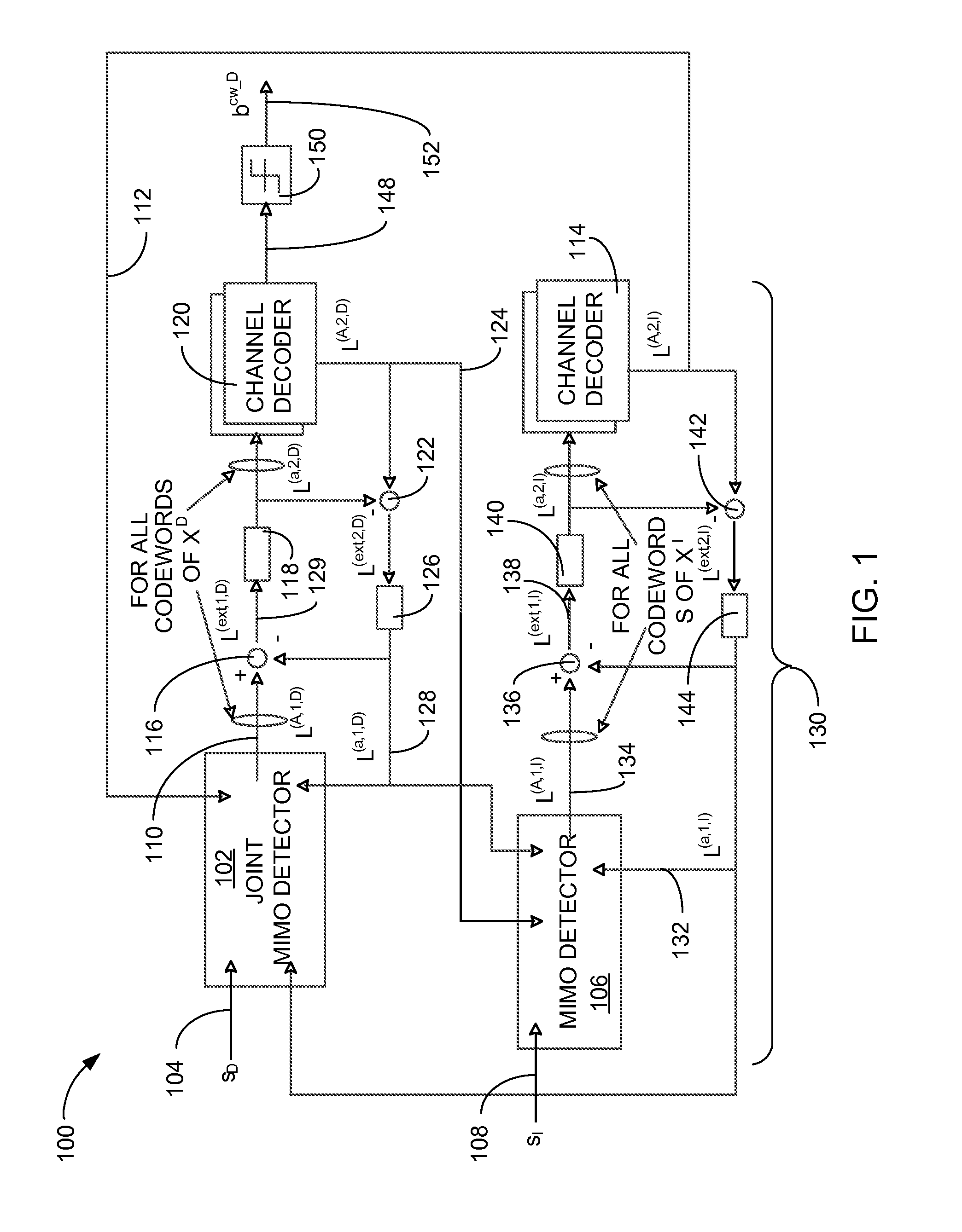
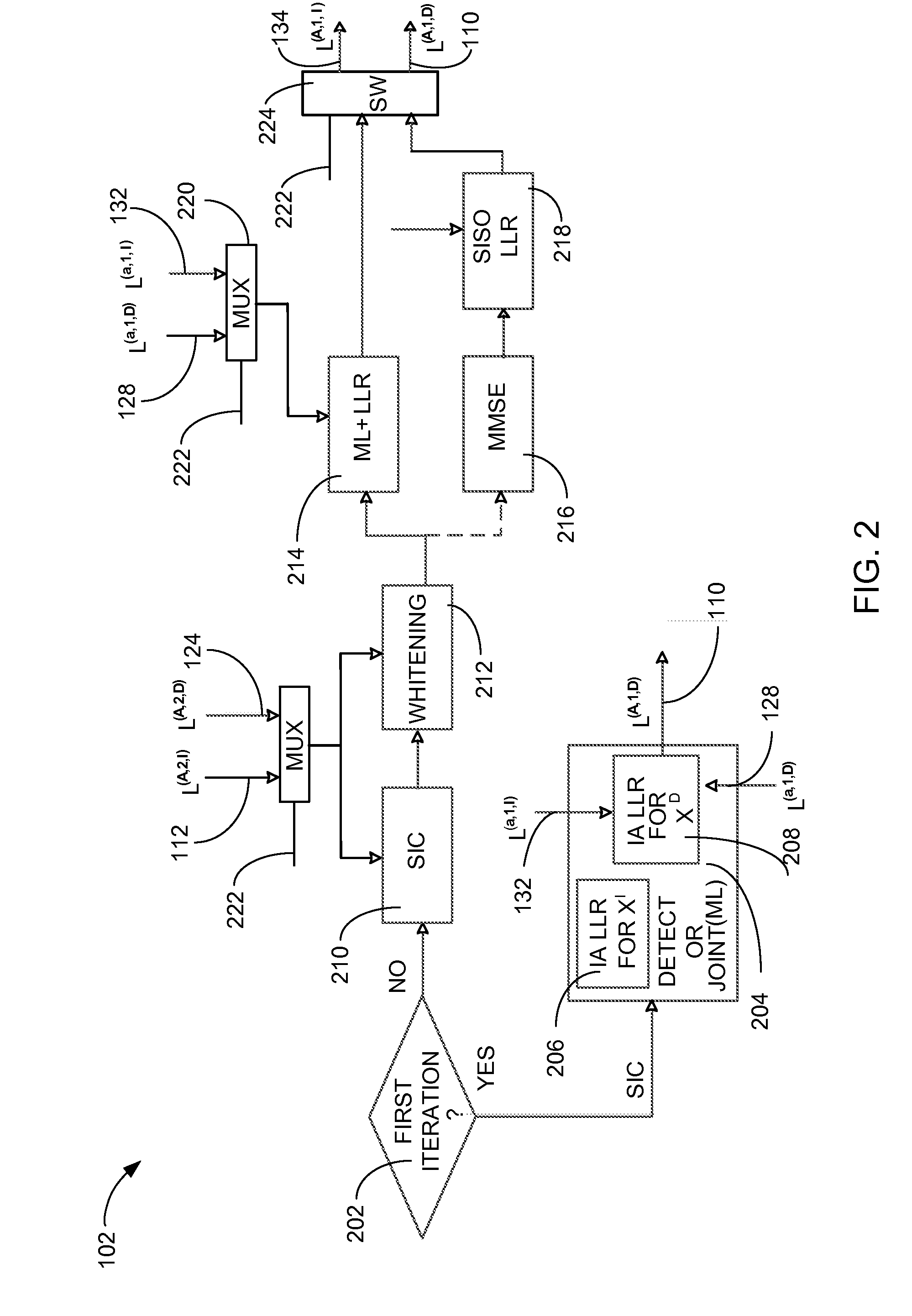
[0021]Referring now to FIG. 1, therein is shown a hardware block diagram of a wireless communication system 100 in the present invention. The hardware block diagram of the wireless communication system 100 depicts a first symbol detector 102, such as a joint multiple input multiple output (J-MIMO) detector, maximum likelihood (ML) detector with interference whitening, or a minimum mean square error (MMSE) detector with interference whitening followed by single-in-single-out (SISO) LLR block, for receiving a desired input signal 104. A second symbol detector 106, such as a multiple input multiple output (MIMO) detector, for receiving an interference input signal 108 that corresponds to the desired input signal 104.

[0022]The desired input signal 104 is defined as the selected input frequency and signal amplitude from a communication source, such as an eNodeB, a wireless base station, a communication transceiver, or a wireless hot spot. The desired input signal 104 can be degraded by t...

second embodiment

[0070]Referring now to FIG. 3, therein is shown a hardware block diagram of a wireless communication system 300 in the present invention. The hardware block diagram of the wireless communication system 300 depicts a first symbol detector 302, such as a joint multiple input multiple output (J-MIMO) detector, maximum likelihood (ML) detector with interference whitening, or a minimum mean square error (MMSE) detector with interference whitening followed by single-in-single-out (SISO) LLR block, for receiving the desired input signal 104. A second symbol detector 304, such as a multiple input multiple output (MIMO) detector, for receiving the interference input signal 108 that corresponds to the desired input signal 104.

[0071]The first symbol detector 302 can include the first interference aware log-likelihood ratio module 206 and the second interference aware log-likelihood ratio module 208. The first interference aware log-likelihood ratio module 206 can calculate the interference log...


PUM


Abstract

A method of operation of a wireless communication system includes: receiving a desired input signal and an interference input signal; activating a first symbol detector for generating a desired log-likelihood ratio from the desired input signal; activating a second symbol detector for generating an interference log-likelihood ratio from the interference input signal; and jointly decoding a decoded bit by iteratively refining the interference log-likelihood ratio for negating the interference input signal and iteratively refining the desired log-likelihood ratio for enhancing the desired input signal.

Description

CROSS-REFERENCE TO RELATED APPLICATION[0001]This application claims the benefit of U.S. Provisional patent application Ser. No. 61 / 576,349 filed Dec. 15, 2011, and the subject matter thereof is incorporated herein by reference thereto in its entirety.TECHNICAL FIELD[0002]The present invention relates generally to a wireless communication system, and more particularly to a system for managing interference in a wireless communication system.BACKGROUND ART[0003]The next generation cellular system, where the cell size is getting smaller so that inter-cell interference becomes a critical issue in terms of packet error performance, is in the process of deployment. In addition, since both pico-cell and femto-cell services were recently launched, the interference signal from these local cells has also become a major source to degrade the performance for the desired signal. In case of a point-to-point communication where a single transmitter sends a signal to the designated receiver, there i...

Claims


Application Information

Patent Timeline
IPC IPC(8): H04B1/10
CPCH04W28/18H04L1/0048H04L1/005H04L1/0054H04L25/03305
Inventor LEE, JUNGWONKWON, HYUKJOONKANG, INYUP
Owner SAMSUNG ELECTRONICS CO LTD
Why Eureka
Try Eureka