Fan unit for a heat exchanger

a technology of fan unit and heat exchanger, which is applied in the direction of engine cooling apparatus, motors, liquid fuel engines, etc., can solve the problems of adversely affecting the overall efficiency of the fan uni

Active Publication Date: 2013-06-20
JOHNSON ELECTRIC SA
View PDF6 Cites 4 Cited by
  • Summary
  • Abstract
  • Description
  • Claims
  • Application Information

AI Technical Summary

Benefits of technology

[0007]Accordingly, in one aspect thereof, the present invention provides a fan unit for a heat exchanger of a motor vehicle, comprising: a plate-like support structure or shroud which has a main opening defining a passage for a flow of air for ventilation of the heat exchanger; and an electric fan mounted in the region of the main opening for inducing the flow of air and including an electric drive motor and an impeller connected to the motor; and the support structure or shroud having a top side intended to extend at a small distance from a horizontal cross-member of the heat exchanger or the motor vehicle, so that an interspace is defined between them, wherein the top side of the support structure or shroud is provided with a flexible sealing gasket having a configuration such that, in the assembled operating condition of the fan unit, the gasket is able to close off the interspace.

Problems solved by technology

Part of the air flow produced by the electric fan escapes through the aforementioned interspace during operation and this adversely affects the overall efficiency of the fan unit.

Method used


Image

  • Fan unit for a heat exchanger
  • Fan unit for a heat exchanger
  • Fan unit for a heat exchanger

Examples


Embodiment Construction

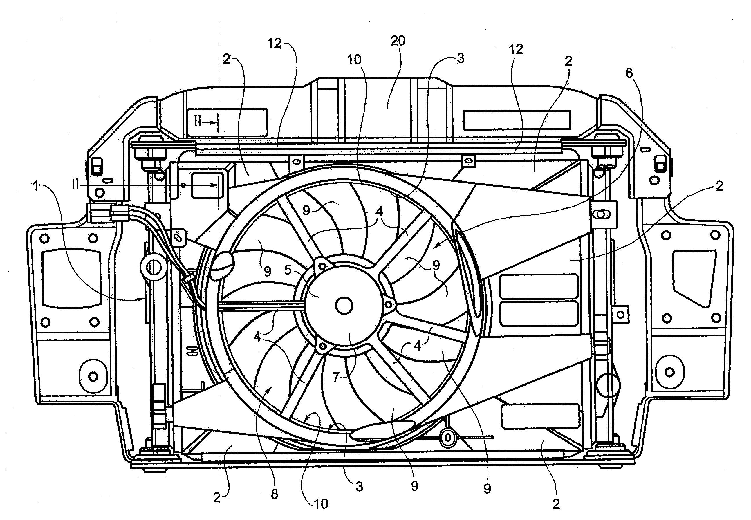
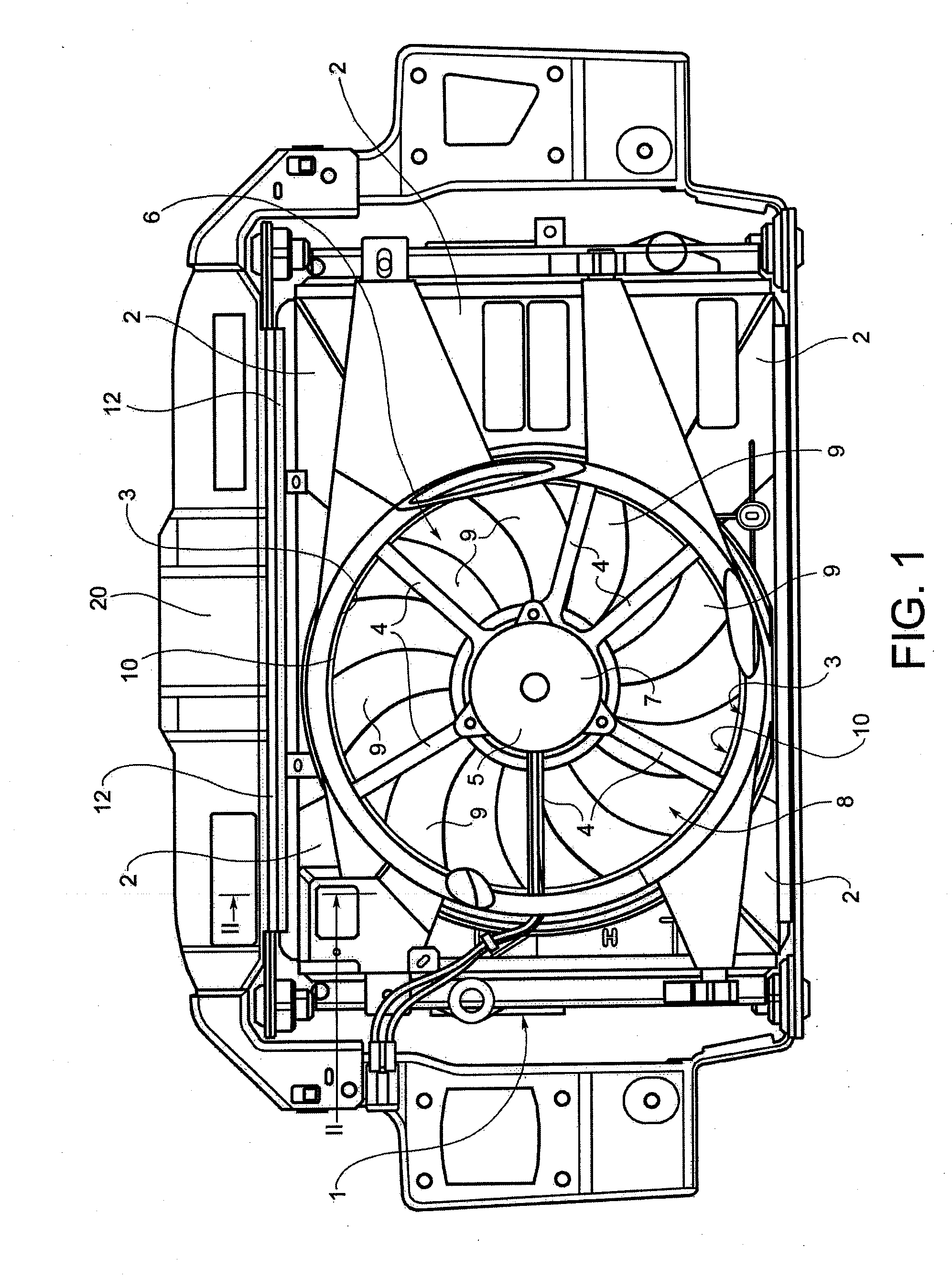
[0019]In FIG. 1 the reference number 1 denotes overall a fan unit according to the preferred embodiment of the present invention for a heat exchanger, such as a radiator, of a motor vehicle. The fan unit 1 comprises essentially a plate-like support structure or shroud 2, for example made of moulded plastic, which has a main opening 3 defining a passage with an essentially circular cross-section for an air flow for ventilation of the heat exchanger. A plurality of spokes 4, which are connected to a central annular support element 5, extend from the edge of the main opening 3. These spokes 4 and the annular support element 5 are conveniently formed as one piece with the support structure or shroud 2.

[0020]The fan unit 1 also comprises an electric fan, denoted overall by 6, which is arranged inside the main opening 3. The electric fan 6 includes an electric drive motor 7 and an impeller 8, with a plurality of blades 9, connected to the motor. The radially outer ends of the blades 9 are...


PUM


Abstract

A fan unit for a heat exchanger of a vehicle, has a plate-like support structure or shroud which has a main opening defining a passage for a flow of air for ventilation of the heat exchanger, and an electric fan arranged to cause the flow of air. The fan has a drive motor and an impeller connected to the motor. The support structure or shroud has a top side intended to extend at a small distance from a horizontal cross-member of the heat exchanger or the vehicle, so that an interspace is defined between them. This top side of the support structure or shroud has a flexible sealing gasket which has a configuration such that, in the assembled operating condition of the fan unit, the gasket is able to close off the interspace.

Description

CROSS REFERENCE TO RELATED APPLICATIONS[0001]This non-provisional patent application claims priority under 35 U.S.C. §119(a) from Patent Application No. TO2011U000141 filed in Italy on Dec. 19, 2011.FIELD OF THE INVENTION[0002]This invention relates to a fan unit for a heat exchanger and in particular, to a fan unit for a heat exchanger of a motor vehicle.BACKGROUND OF THE INVENTION[0003]The present invention relates to a fan unit for a heat exchanger, in particular a radiator, of a motor vehicle.[0004]More specifically the invention relates to a fan unit for a heat exchanger, of the type comprising: a plate-like support structure, or shroud, which has a main opening defining a passage for a flow of air for ventilating the heat exchanger; and an electric fan mounted on the support structure or shroud and arranged in the region of the main opening to induce the flow of air through the main opening. The fan includes an electric drive motor and an impeller connected to the motor. The p...

Claims


Application Information

Patent Timeline
Patent Type & Authority Applications(United States)
IPC IPC(8): F04D29/64
CPCF04D29/646F04D29/601F01P2005/046F01P11/10F01P5/06F01P5/02F01P11/00F16J15/10
Inventor MURADOR, FRANCESCOTENCO, VALENTINO
Owner JOHNSON ELECTRIC SA
Why Eureka
Try Eureka