Rail vehicle having a device for finishing the running surface of track rails

a technology for finishing the running surface and track rails, which is applied to railway tracks, carriages, milling equipment, etc., can solve the problems of substantial difficulty in machine track rails having small curve radii

Inactive Publication Date: 2017-11-02
LINSINGER MASCHENBAU GES
View PDF18 Cites 2 Cited by
  • Summary
  • Abstract
  • Description
  • Claims
  • Application Information

AI Technical Summary

Benefits of technology

[0011]Because the transverse carriage forming the milling head receptacle remains free on the upper and lower sides as a result of a lateral guide path of the transverse carriage, the guide stop for the transverse guide of the milling head receptacle can advantageously be applied to the railhead below the milling head, which provides particularly advantageous design conditions with respect to the transverse guide of the milling head.

Problems solved by technology

However, such a system is disadvantageous in that the rail vehicle requires a special design of the chassis frame, and a comparatively large diameter of the milling head, which necessarily results from the proposed design, requires correspondingly large axle distances between the wheel sets of the rail vehicle upstream and downstream of the milling device, which makes it substantially more difficult to machine track rails having small curve radii, as occur in subways, for example.
Similar disadvantages result in the case of another known milling device (disclosed, for example, in WO 2013 / 086547 A1), in which the milling head is adjustable with the aid of a compound carriage, which is upstream in the travel direction and which is composed of a transverse carriage and a vertical carriage.

Method used


Image

  • Rail vehicle having a device for finishing the running surface of track rails
  • Rail vehicle having a device for finishing the running surface of track rails
  • Rail vehicle having a device for finishing the running surface of track rails

Examples


Embodiment Construction

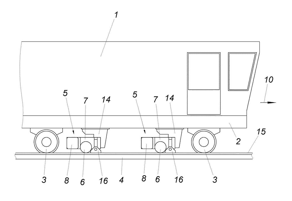
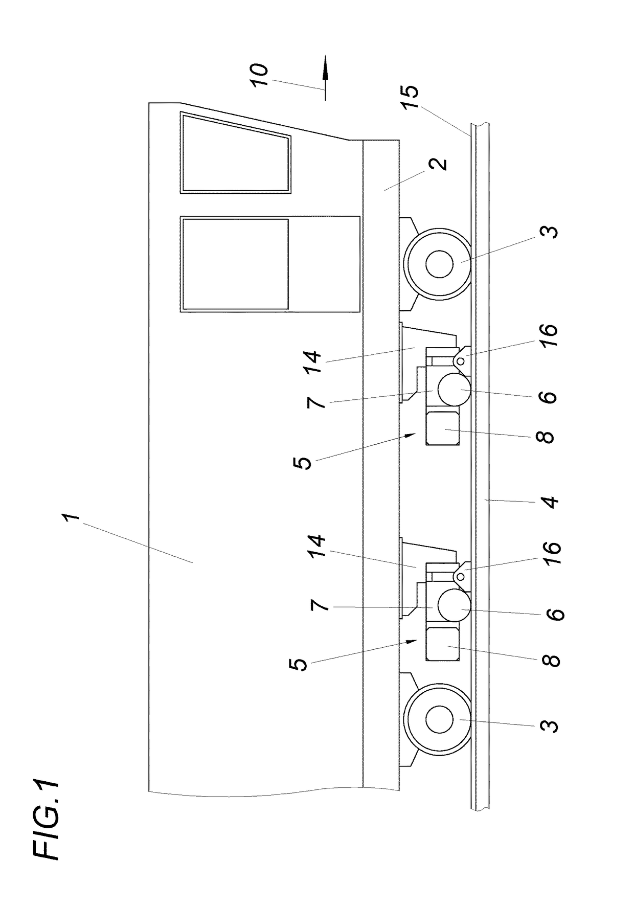
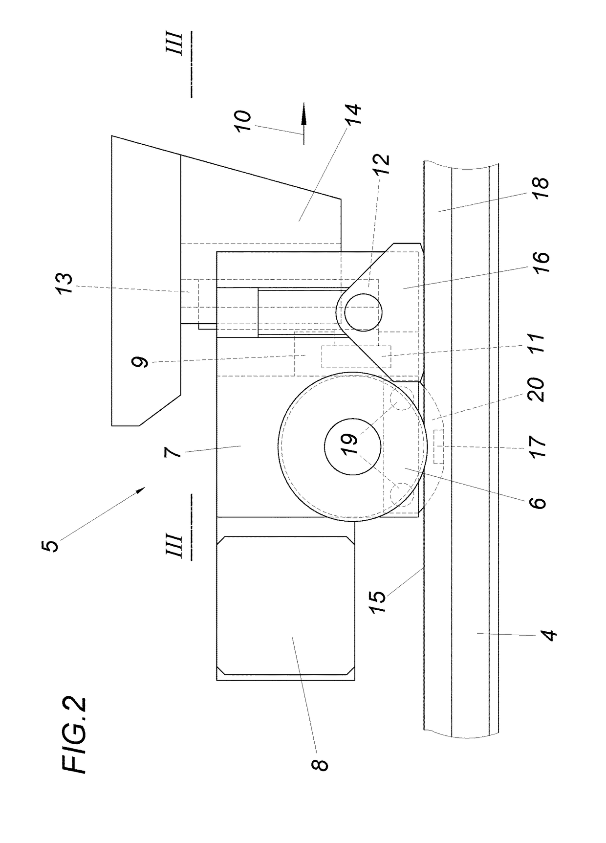
[0018]The rail vehicle 1 has, according to FIG. 1, a chassis frame 2 having wheel sets 3, which roll on track rails 4. Two corresponding milling devices 5 for the track rails 4 are arranged between each of the wheel sets 3 below the linear continuous chassis frame 2. The milling devices 5 have a milling head 6, which is mounted in a milling head receptacle 7 and is driven in a way known per se via a motor 8. The milling head receptacle 7 forms, according to FIGS. 2 and 3, a transverse carriage 9, which is guided in parallel to the milling head shaft in a guide path 11, which is upstream from the milling head receptacle 7 with respect to the travel direction 10. The guide path 11 for the transverse carriage 9, which is opposite to the motor 8 for the milling head drive with respect to the milling head receptacle, is displaceable vertically via a feed carriage 12, which is held so the feed carriage 12 is displaceable in a guide 13 of a framework 14. The positioning drives for the tran...


PUM

PropertyMeasurementUnit
diameteraaaaaaaaaa
heightaaaaaaaaaa
curve radiiaaaaaaaaaa

Abstract

A rail vehicle includes a milling device for finishing the running surface of track rails during the travel of the rail vehicle along the track rails. The rail vehicle has a chassis frame having wheel sets. The milling device is provided with a milling head, and includes a framework arranged on the chassis frame having a milling head receptacle, which is displaceable vertically and transversely in relation thereto. The milling head receptacle can be supported for the vertical guiding via a guide shoe on the running surface and for transverse guiding in parallel to the milling head shaft via a guide stop laterally on the railhead. The milling head receptacle forms a transverse carriage, which supports the guide shoe and the guide stop, and the guide path of which, which is vertically displaceable, is provided on the side of the milling head receptacle facing toward the guide shoe.

Description

1. FIELD OF THE INVENTION[0001]The system described herein relates to a rail vehicle and more particularly to rail vehicle for finishing a surface of track rails.2. DESCRIPTION OF THE PRIOR ART[0002]In rail vehicles for finishing the running surface of track rails, providing a chassis frame with a passage opening for the milling device is known (EP 0 952 225 A1). Such systems avoid having to provide an upwardly protruding chassis frame for housing the milling device below the chassis frame. The milling head shaft extends above the chassis frame and is mounted in a vertical carriage, which is guided in a transverse carriage, so that the milling head can be guided correctly for the machining via upstream and downstream support rollers, which are provided with wheel flanges, as the milling head travels along the running surfaces of the track rails as a slotted guide. Because of the passage opening in the chassis frame of the rail vehicle and the arrangement of the milling head shaft ab...

Claims


Application Information

Patent Timeline
Patent Type & Authority Applications(United States)
IPC IPC(8): E01B31/13B23C3/00
CPCE01B31/13B23C2220/28B23C2215/32B23C3/005E01B31/12Y10T408/5565Y10T409/306384Y10T409/30672B61D15/00E01B2203/141B23C1/007
Inventor RUNGGER, HELMUT
Owner LINSINGER MASCHENBAU GES
Why Eureka
Try Eureka