System for wireless remote monitoring of alarm events of a medical device and corresponding patient

a wireless remote and alarm technology, applied in the field of life-critical medical equipment, can solve the problems of no wireless remote alarm transfer system commercialized for ventilation equipment, insufficient in many clinical situations, and significant limitations, and achieve the effect of reliable and convenient means

Inactive Publication Date: 2013-06-20
ILIFF DENE ROBERT +1
View PDF11 Cites 38 Cited by
  • Summary
  • Abstract
  • Description
  • Claims
  • Application Information

AI Technical Summary

Benefits of technology

[0010]The present invention describes a system to remotely and wirelessly receive alarm information from a life-critical medical dev

Problems solved by technology

While the remote wired alarm transfer devices help alert a caregiver to a problem when the caregiver is not in the immediate vicinity of the patient, they have significant limitations.
To date, there has been no wireless remote alarm transfer systems commercialized for ventilation equipment, although some have been described in the literature.
Those described have various drawbacks as will be described later, and because of those drawbacks they will simply not suffice in many clinical situations.
These systems are not cross-compatible with ventilators across brands, and are not cross-compatible with different models of same brand ventilators, necessitating multiple models.
Because of their non-compatibility across models, the manufacturers must carry different model alarm units for different model ventilators.
This is a significant logistical and cost disadvantage.
When switching out ventilators, the remote alarm unit will have to be also switched out, therefore increasing costs.
To date, there have been no universally compatible remote alarm systems described to solve this problem.
These remote alarm systems are also limited in their utility because they are hard wired systems.
However, this system has significant drawbacks and limitations including (1) the system requires attachment to the gas delivery circuit and

Method used


Image

  • System for wireless remote monitoring of alarm events of a medical device and corresponding patient
  • System for wireless remote monitoring of alarm events of a medical device and corresponding patient
  • System for wireless remote monitoring of alarm events of a medical device and corresponding patient

Examples


Embodiment Construction

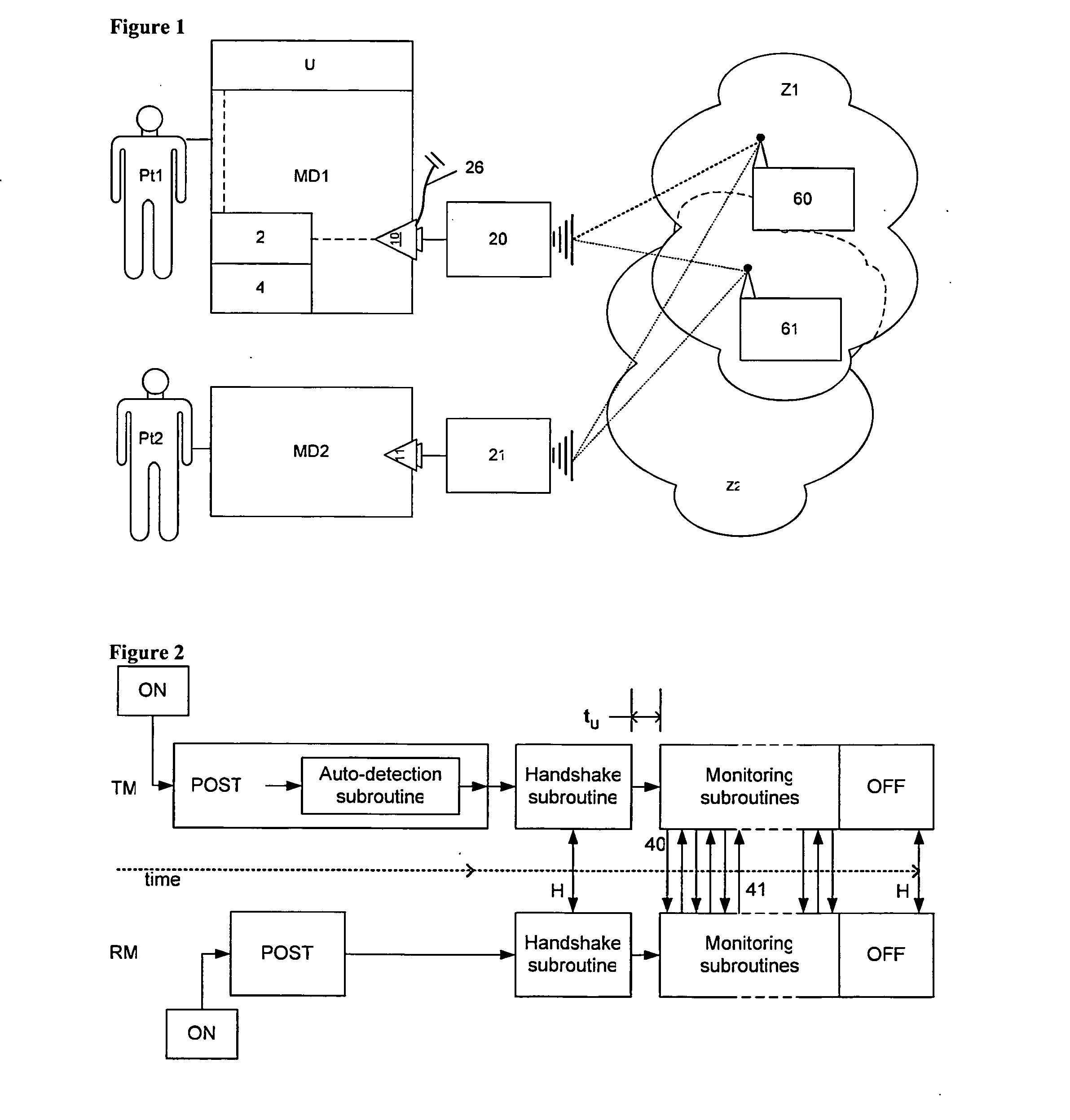
[0056]FIG. 1 describes an overall schematic of the invention. A medical device is being used to support a patient, such as a ventilator being used for respiratory support. The device typically includes a control subsystem and monitoring subsystem to control the operation of the device, and to monitor the operation of the medical device respectively. Often, the monitoring system detects problems with the patient or the medical device. The problems are typically communicated to a clinician or caregiver in the proximity of the patient and the medical device via a user interface. The user interface typically includes both audible and visual alarms, alerts, and messages. These information are typically prioritized into dire and non-dire events. Often, a critical care medical device has an alarm event output outlet connector and circuit, so that a wired remote alarm unit can be connected to the outlet, allowing the alarm status to be monitored remotely. The alarm unit is typically a box o...


PUM


Abstract

A wireless remote alarm system is described to allow a mobile caregiver or clinician to track the alarm status of a life-critical medical device and patient while the caregiver or clinician is located away from the patient. The system includes automatic recognition of the medical device's alarm output circuit for universal compatibility, in order to render the system practical, convenient and reliable to deploy, and protocols for signal reliability, security and power management. The system also includes alarm differentiation protocols to assist the caregiver with alarm prioritization, and remote patient management applications via wider-area network connectivity. The system is especially useful in alternate care and homecare settings, and for monitoring patients using a ventilator.

Description

PRIORITY CLAIM[0001]This application claims priority to U.S. Provisional Patent Applications 61 / 488,723 filed on May 21, 2011 and 61 / 577,194 filed on Dec. 19, 2011.FIELD OF THE INVENTION[0002]The present invention relates to the field of life critical medical equipment, and more specifically to wireless remote monitoring of alarm conditions related to patients being treated with life critical equipment.BACKGROUND OF THE INVENTION[0003]Various forms of critical and life-supporting medical equipment are commonplace in the hospital setting and home care setting. Some examples of critical equipment include: life-critical respiratory support in which a patient is dependent on a respiratory ventilator, oxygen therapy devices, heart assist devices, kidney treatment devices, infusion devices, and in the case of neonatal care, incubators. For brevity purposes throughout the descriptions herein, respiratory ventilators are used as an example. These equipment typically include alarms to alert ...

Claims


Application Information

Patent Timeline
IPC IPC(8): H04B7/26H04B17/00
CPCH04W52/0245H04W52/0261Y02B60/50A61B5/0022A61B5/08A61M16/0051A61M2205/8212A61M2205/3553A61M2205/3561A61M2205/3584A61M2205/3592A61M2205/502A61M2205/18A61M16/021G16H40/20G16H40/67Y02D30/70
Inventor WONDKA, ANTHONY DAVIDILIFF, DENE
Owner ILIFF DENE ROBERT
Why Eureka
Try Eureka