Eureka AIR delivers breakthrough ideas for toughest innovation challenges, trusted by R&D personnel around the world.

Roller-type friction transmission unit

Inactive Publication Date: 2013-06-20
NISSAN MOTOR CO LTD
View PDF8 Cites 4 Cited by
  • Summary
  • Abstract
  • Description
  • Claims
  • Application Information

AI Technical Summary

Benefits of technology

The patent describes a new roller-type friction transmission unit that solves the problem of judder (noise, vibration) between the rollers during power transmission. The unit achieves this by designing the outer surfaces of the rollers to be in contact with each other at multiple points, which lowers the inter-roller contact pressure and reduces the range of negative gradient in the traction coefficient. This allows for smooth power transmission even in the range of negative gradient and suppresses judder from occurring between the rollers.

Problems solved by technology

Accordingly, if the parallelism between the roller rotation axes is lowered by errors in assembling or errors in precision of parts, it significantly adversely affects the endurance and transmission efficiency of the roller-type friction transmission unit.
In this way, it is disadvantageous in view of robustness.
However, in the case of the conventional roller-type friction transmission unit described above, the configuration that roller outer peripheral surfaces are in frictional contact with each other at a single point may raise the contact pressure between the rollers at that contact point, and thereby cause the following problem.
In a conventional roller-type friction transmission unit, the feature that the roller outer peripheral surfaces are in contact with each other only at one point, and the inter-roller contact pressure at that point is high, results in that the μ-V characteristic has the tendencies (1)-(3) described above as indicated by a solid line in FIG. 5, so that smooth power transmission is difficult in the range of negative gradient of the μ-V characteristic, wherein judder (noise, vibration) tends to occur between the rollers.

Method used


Image

  • Roller-type friction transmission unit
  • Roller-type friction transmission unit
  • Roller-type friction transmission unit

Examples


first embodiment

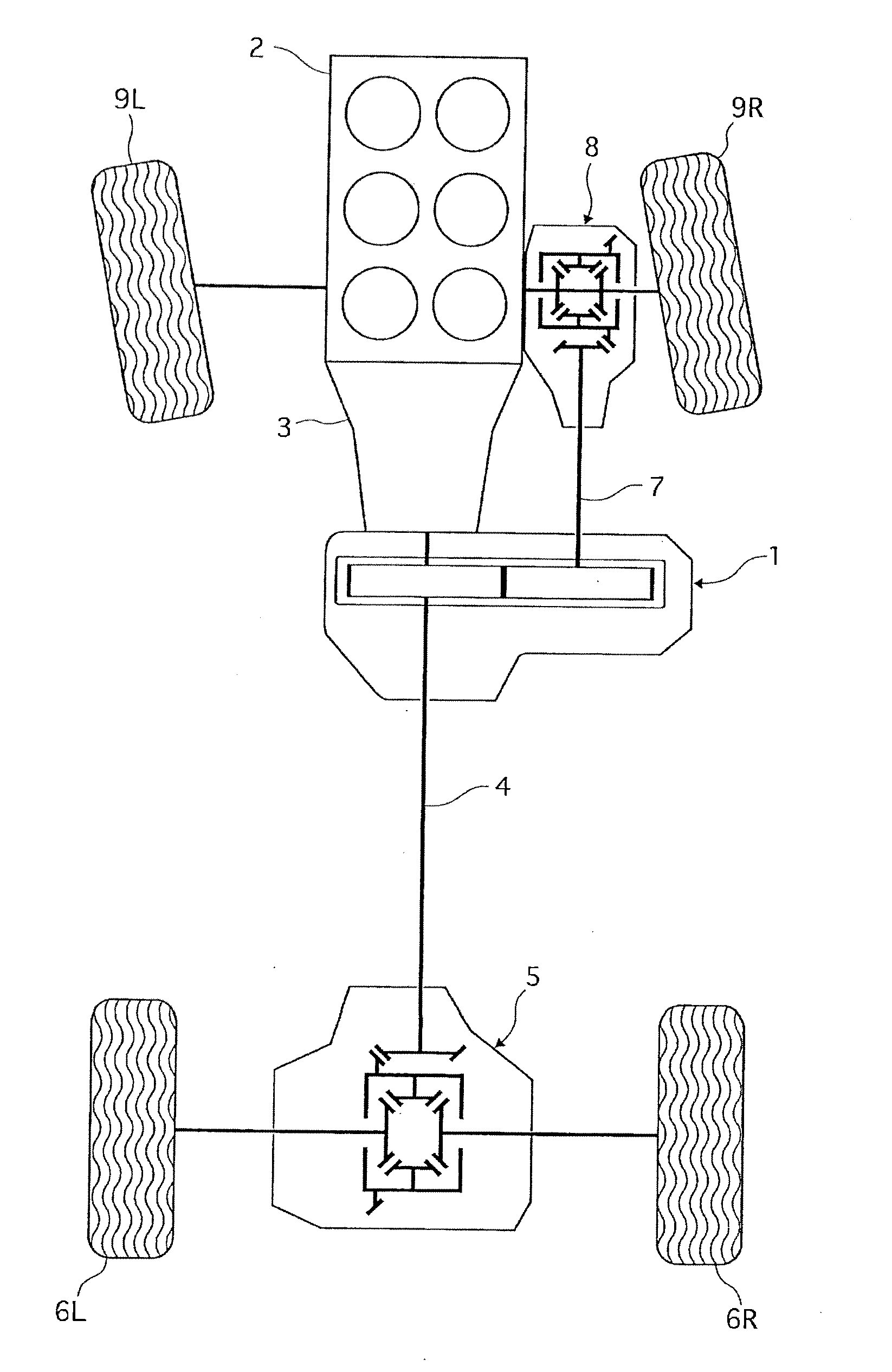
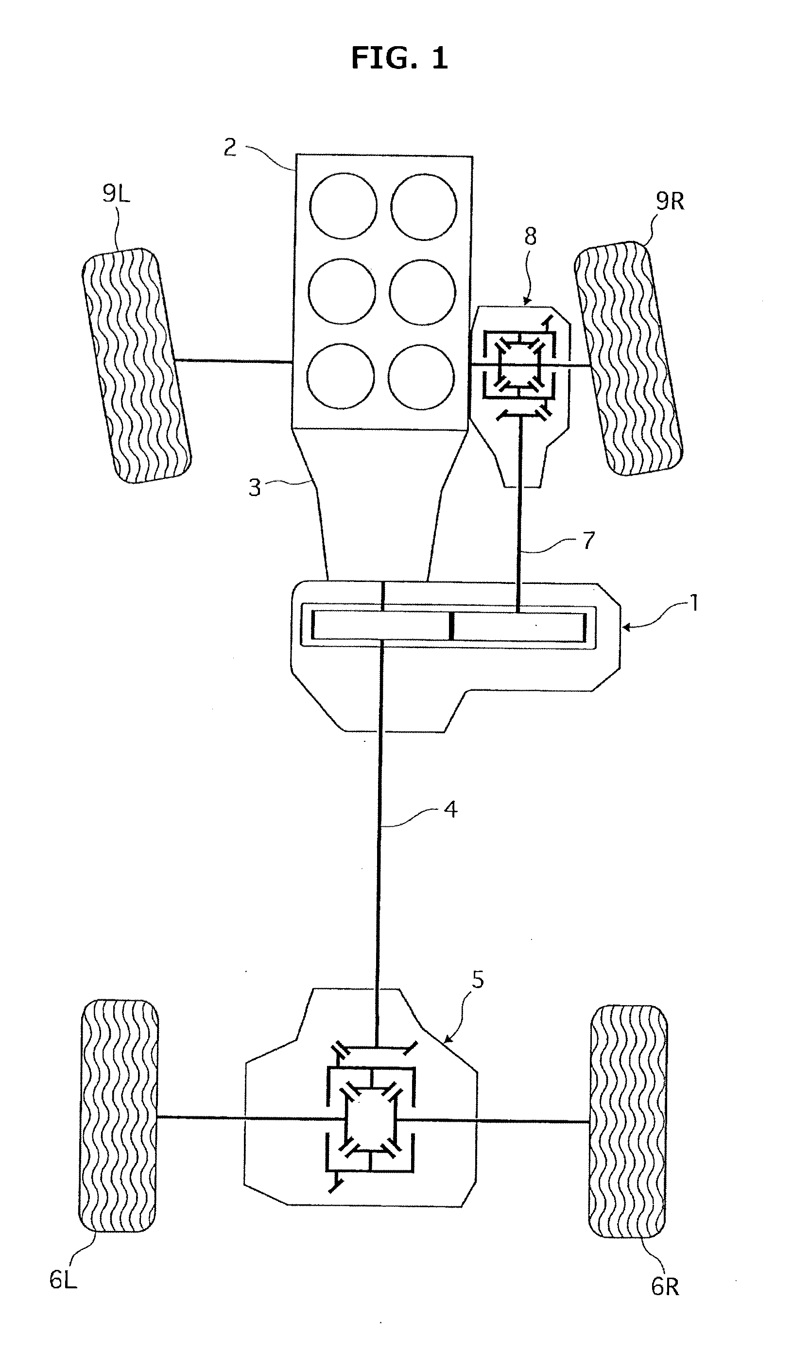
[0023]FIG. 1 is a schematic plan view from above a four wheel drive vehicle, showing a powertrain of the four wheel drive vehicle which is provided with a roller-type friction transmission unit 1 according to the present invention.

[0024]The four wheel drive vehicle of FIG. 1 is based on a rear wheel drive vehicle in which rotation from an engine 2 is shifted by a transmission 3, and then transmitted through a rear propeller shaft 4 and a rear final drive unit 5 to left and right rear wheels 6L, 6R, and constructed so that a part of torque to left and right rear wheels (main driving wheels) 6L, 6R is transmitted by roller-type friction transmission unit 1 through a front propeller shaft 7 and a front final drive unit 8 to left and right front wheels (auxiliary driving wheels) 7L, 7R, thus achieving four wheel driving.

[0025]Roller-type friction transmission unit 1 is thus configured to set a torque distribution ratio between left and right rear wheels (main driving wheels) 6L, 6R, and...

second embodiment

[0051]FIG. 3 shows a roller-type friction transmission unit according to the present invention. In this embodiment, the outer peripheral surface 21a of first roller 21 is formed as a single convex surface 21e including a relatively raised portion middle in the axial direction, and the outer peripheral surface 22a of second roller 22 is formed as a V-groove surface 22b, 22c including a relatively recessed portion middle in the axial direction.

[0052]By this construction, the outer peripheral surface 21a of first roller 21 formed as single convex surface 21e is in frictional contact with the V-groove surface 22b of second roller 22 constituting the outer peripheral surface 22a of second roller 22 at spot β1, whereas the outer peripheral surface 21a of first roller 21 formed as single convex surface 21e is in frictional contact with the V-groove surface 22c of second roller 22 constituting the outer peripheral surface 22a of second roller 22 at spot β2. Namely, the outer peripheral surf...


PUM


Abstract

In a roller-type friction transmission unit, outer peripheral surfaces of first and second rollers are pressed in a radial direction into pressing contact with one another, to allow frictional power transmission between the first and second rollers. The first roller is connected to a driveline to main driving wheels of a four wheel drive vehicle. The second roller is connected to a driveline to auxiliary driving wheels of the four wheel drive vehicle. The transmitted torque capacity between the first roller and the second roller is controlled by changing a distance between rotation axes of the first and second rollers. The outer peripheral surfaces of the first and second rollers are shaped to allow the outer peripheral surfaces of the first and second rollers to be in contact with one another at a plurality of spots arranged in an axial direction.

Description

DESCRIPTION[0001]1. Technical Field[0002]The present invention relates to a roller-type friction transmission unit which is used as a transfer of a four wheel drive vehicle, and particularly relates to a technique for suppressing judder (noise, vibration) occurring between rollers in the roller-type friction transmission unit.[0003]2. Background Art[0004]Such a roller-type friction transmission unit is known as is described in a patent document 1. The roller-type friction transmission unit described in this document includes a pair of rollers, wherein an outer peripheral surface of a first roller and an outer peripheral surface of a second roller are pressed in a radial direction of the first and second rollers into pressing contact with one another, to allow frictional power transmission between the first and second rollers; the first roller is connected to a driveline to main driving wheels of a four wheel drive vehicle; and the second roller is connected to a driveline to auxilia...

Claims


Application Information

Patent Timeline
IPC IPC(8): F16H13/04
CPCF16H13/02B60K17/344F16H13/04
Inventor TAKAISHI, TETSU
Owner NISSAN MOTOR CO LTD
Why Eureka
Eureka Blog
Learn More