
Photo-electrochromic window tinter

a technology of photoelectrochromic window and tinting, applied in the direction of optical radiation measurement, instruments, navigation instruments, etc., can solve the problems of vehicle owners being cited by law enforcement agencies, affecting the visibility of windows, and obscuring or reducing the ability of drivers to s

Active Publication Date: 2013-06-20
CONTINENTAL AUTOMOTIVE SYST INC
View PDF5 Cites 108 Cited by
  • Summary
  • Abstract
  • Description
  • Claims
  • Application Information

AI Technical Summary

Benefits of technology

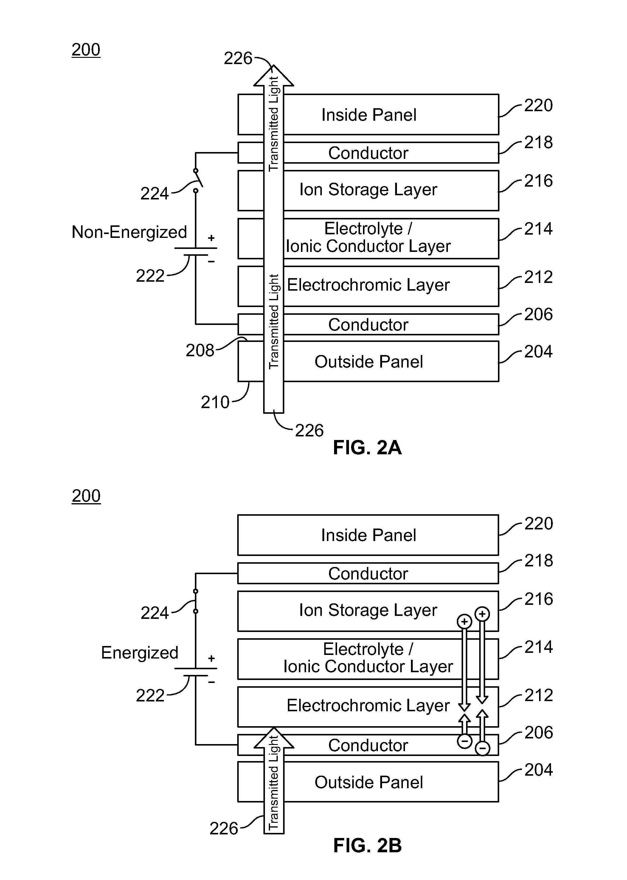
The patent text describes a system for controlling the tinting of vehicle windows to reduce solar heating and protect the interior of the vehicle from damage caused by sunlight. The system uses an electrochromic device that can be applied to window glass to adjust the amount of light that can pass through. The device is controlled by a control voltage or current source, which can be applied or removed from the conductors using a switch mechanism. The system allows for the tinting of windows to be adjusted based on the vehicle's location and the laws and regulations in that location. The technical effect of the system is to provide the benefits of tinted windows without the risk of legal or local citation.

Problems solved by technology

Unfortunately, window tinting can obscure or reduce a driver's ability to see and they are known by law enforcement to conceal the interior of a vehicle.
If a vehicle owner applies window tinting to a vehicle that is permitted by local ordinances but prohibited by the ordinances of surrounding jurisdictions, the vehicle owner risks being cited by law enforcement agencies in jurisdictions where vehicle window tinting is prohibited.

Method used


Image

  • Photo-electrochromic window tinter
  • Photo-electrochromic window tinter
  • Photo-electrochromic window tinter

Examples


first embodiment

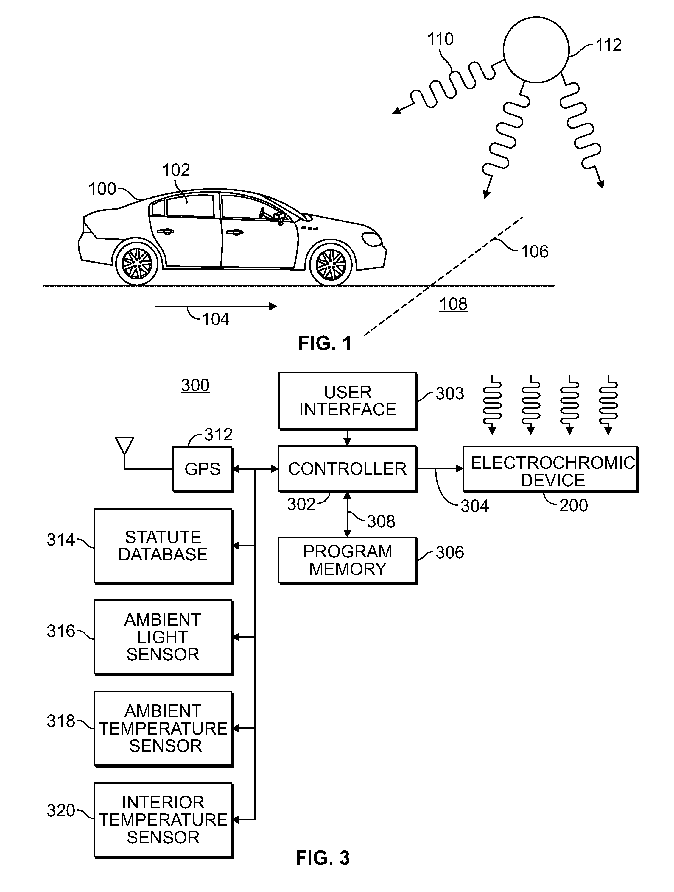
[0019]In a first embodiment, of the photo-electrochromic window tinter 300, the controller 302 queries the GPS receiver 312 for geographic coordinates, i.e., a location of where the vehicle is located. The location of the tinter or a vehicle it is attached to is provided to the controller in latitude and longitude coordinates. The controller 302 thereafter queries the window tinting rules database 314 to determine whether the current location of the vehicle is inside of a jurisdiction where tinted windows are prohibited, or if there is a tinted window opacity specification, i.e., a rule or law that dictates the darkness or degree to which a window tint passes light, which needs to be complied with.

second embodiment

[0020]In a second embodiment, which is useful for all vehicles but especially useful to electrically-powered vehicles, the controller 302 queries the ambient light sensor, ambient temperature sensor, and / or the interior temperature sensor 320 to adjust the tinting on the electrochromic device 200 to optimize interior temperatures responsive to interior and exterior conditions.

[0021]FIG. 4 depicts a method 400 of adjusting a window tint responsive to a geographic location. A method is performed by a controller or computer such as the controller 302 depicted in FIG. 3 and described above.

[0022]At step 402, the controller obtains its current location from a navigation system such as the GPS system 312 depicted in FIG. 3. Once the location is obtained from the GPS, a database is consulted at step 404 to determine or locate window tinting rules that apply to where the vehicle is located. As used herein, a window tinting rule is a statute or ordinance or other law or regulation that defin...


PUM


Abstract

An electrically-adjustable light transmitter changes its light transmissivity responsive to an electric signal. By applying the electrically-adjustable light transmitter to a window and thereafter changing the electric signal to it, a window can be tinted and un-tinted. Jurisdictions that prohibit tinted vehicle windows are listed in a data base. A current location determined by a GPS is compared to data base entries. If the location is within an area where tinted windows are prohibited, a controller automatically un-tints the windows, or reduces the window tint to comply with applicable local laws.

Description

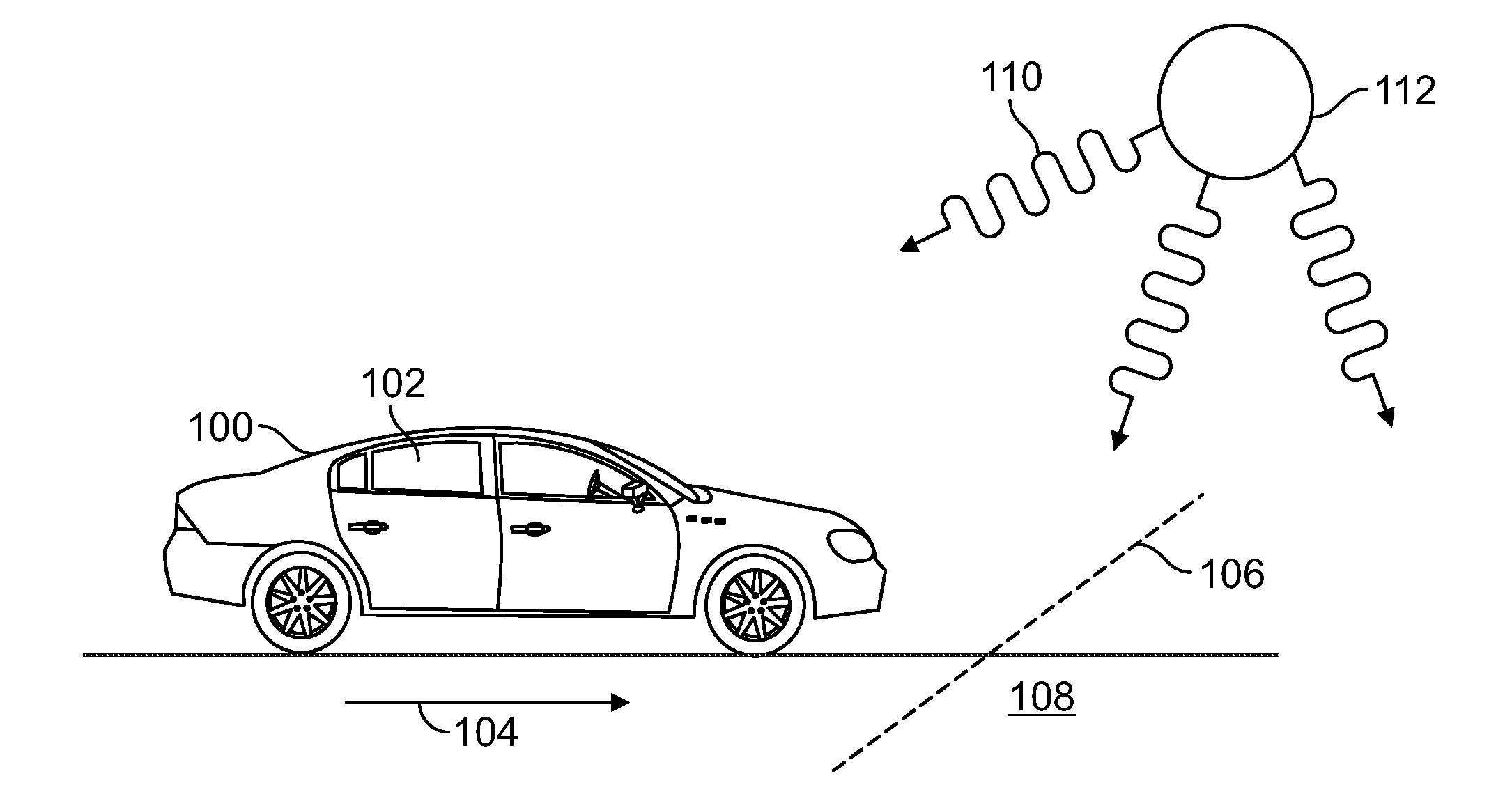
BACKGROUND[0001]Tinted vehicle windows are well known to reduce solar heating of a vehicle. Since they reduce the amount of ultraviolet and infrared that enters a vehicle's interior they also tend to protect the materials from which dashboards and interior surfaces are made. Unfortunately, window tinting can obscure or reduce a driver's ability to see and they are known by law enforcement to conceal the interior of a vehicle. Some states, counties, and municipalities prohibit tinted windows of any kind while other jurisdictions specify or define the maximum tinting or opacity that vehicle window glass can have. If a vehicle owner applies window tinting to a vehicle that is permitted by local ordinances but prohibited by the ordinances of surrounding jurisdictions, the vehicle owner risks being cited by law enforcement agencies in jurisdictions where vehicle window tinting is prohibited.BRIEF DESCRIPTION OF THE DRAWINGS[0002]FIG. 1 depicts a motor vehicle with tinted windows leaving ...

Claims


Application Information

Patent Timeline
IPC IPC(8): G06F7/00G01J1/44G01C21/26G02F1/163
CPCG02F1/163B60J3/04G02F1/1533
Inventor MCINTYRE, JR., WILLIAM E.ANDERSON, JERREMY H.WHITMORE, TOD R.
Owner CONTINENTAL AUTOMOTIVE SYST INC
Learn More