Dual fuel injector having fuel leak seals

a dual fuel injector and fuel leak technology, which is applied in the direction of liquid fuel feeders, machines/engines, mechanical equipment, etc., can solve the problems of continuous diesel fuel leakage into the natural gas orifice, combustion gas intrusion after ignition in some dual fuel injectors, and failure to teach an injector that can independently receive two fluids

Inactive Publication Date: 2013-06-27
CATERPILLAR INC
View PDF14 Cites 47 Cited by
  • Summary
  • Abstract
  • Description
  • Claims
  • Application Information

AI Technical Summary

Benefits of technology

[0005]In accordance with one embodiment, the present disclosure is directed to a dual fuel injector. The dual fuel injector includes an injector body, a nozzle, a first fuel check needle, a second fuel check needle, a fuel separator, and at least one sealing member. The injector body is configured to receive a first fuel and a second fuel. The nozzle is configured with a first set of orifices for injecting the first fuel and a second set of orifices for injecting the second fuel. The first fuel check needle is disposed in a first fuel check cavity, wherein the first fuel check needle defines an interior cavity. The second fuel check needle is positioned within the interior cavity of the first fuel check needle. The second fuel check needle is movable within a second fuel check cavity. The fuel separator configured with a first end and a second end is disposed in the interior cavity between the first fuel check needle and the second fuel check needle. The second end of the fuel separator is disposed in sealing contact with the nozzle. The fuel separator is configured to prevent commingling of the first fuel and the second fuel. At least one sealing member is configured to prevent the second fuel from leaking from the second fuel check cavity into the first set of orifices.
[0006]In another aspect, a dual fuel common rail fuel system including a first fuel source, a second fuel source, a first fuel rail, a second fuel rail, at least one first fuel pump configured to pressurize the first fuel from the first fuel source and ...

Problems solved by technology

However, in some of these dual fuel injectors, there is an issue of continuous diesel fuel leakage from the fuel cavity into the natural gas orifice, and then into the combustion chamber.
Further, combustion gas intrusion after ignition ...

Method used


Image

  • Dual fuel injector having fuel leak seals
  • Dual fuel injector having fuel leak seals
  • Dual fuel injector having fuel leak seals

Examples


Embodiment Construction

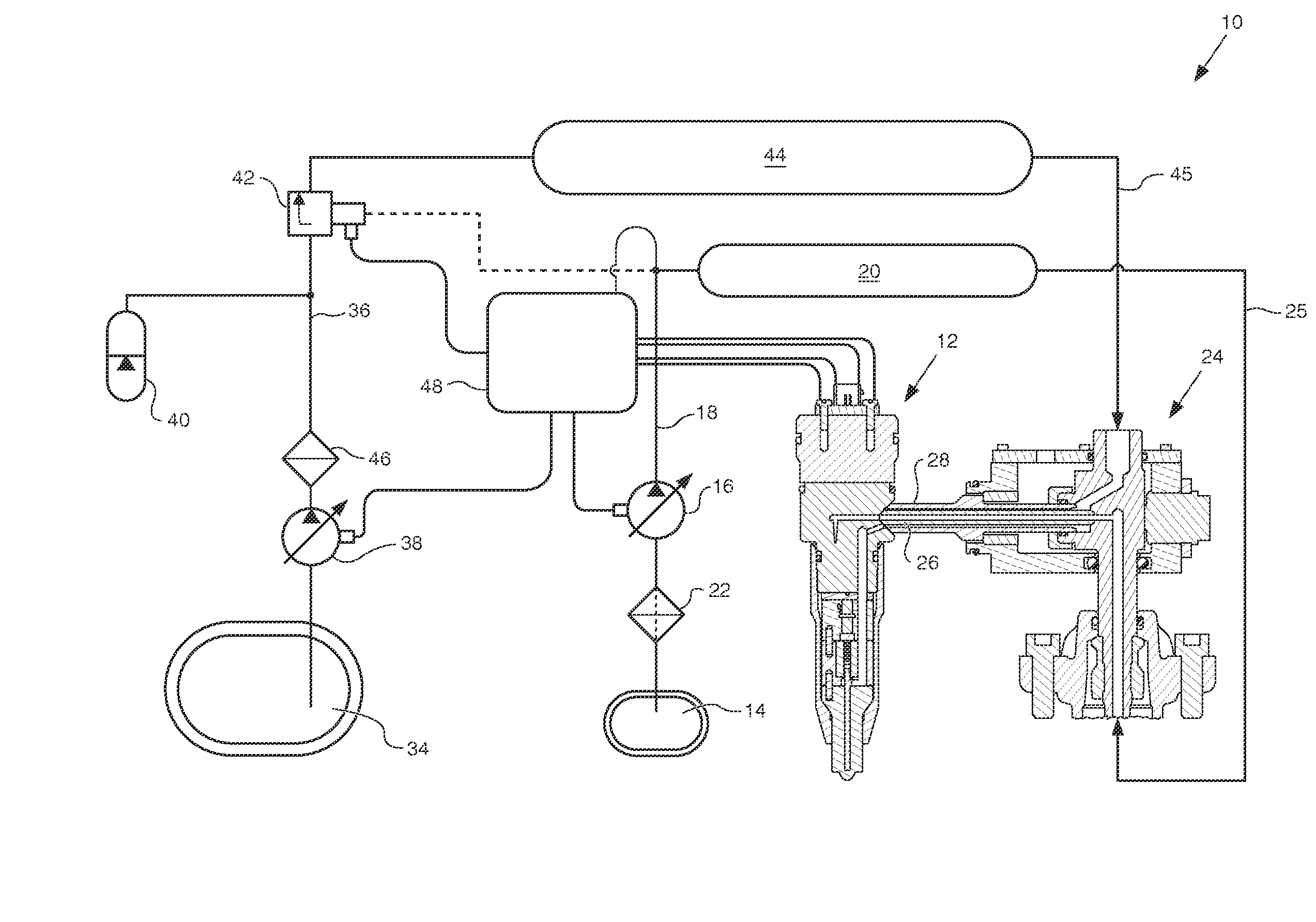
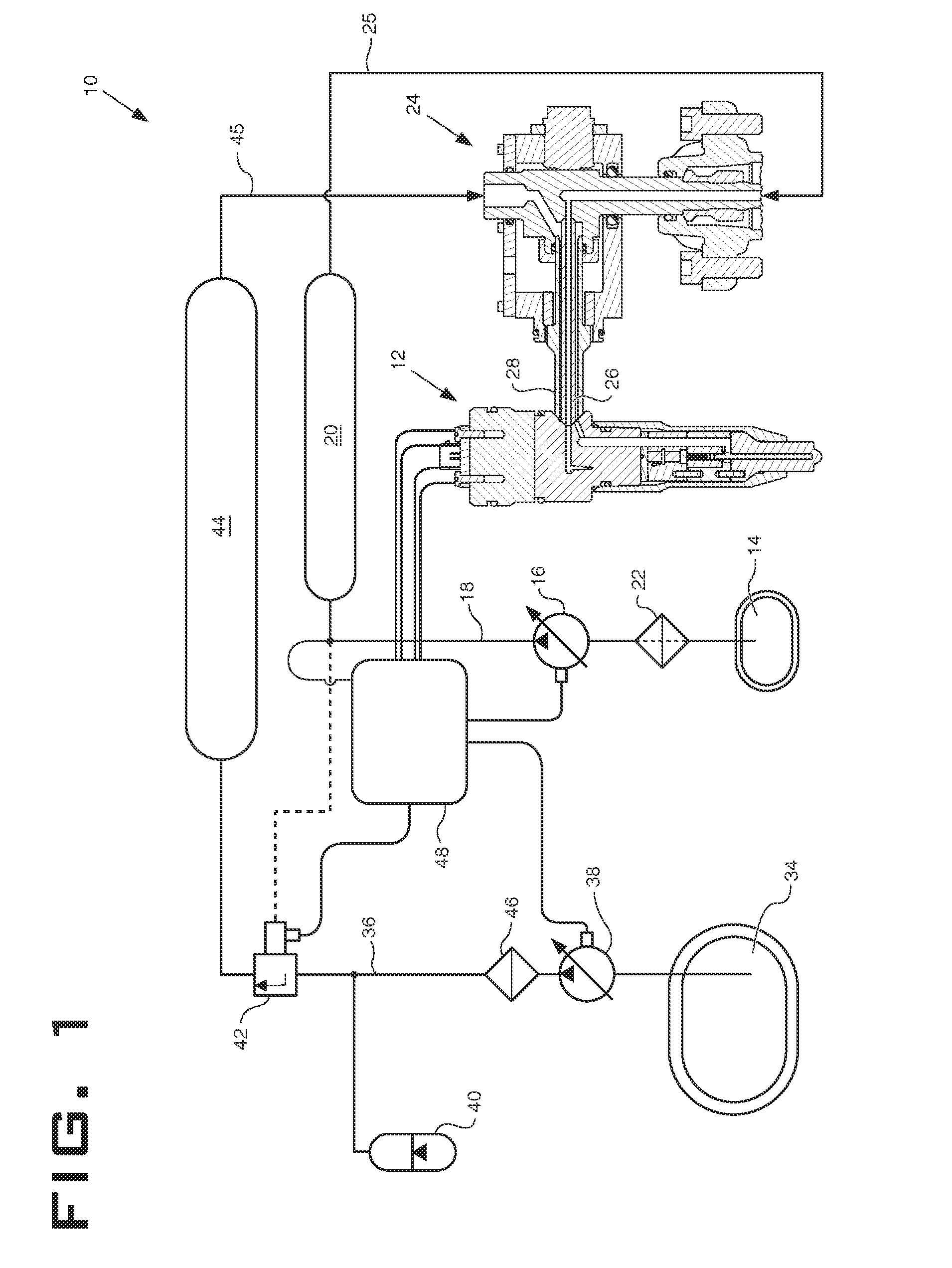
[0015]Referring to FIG. 1, a dual fuel common rail fuel system 10 utilizing a dual fuel common rail injector 12 is shown. For ease of discussion, the dual fuel common rail injector will be referred to as “injector 12”. A diesel fuel source 14 contains diesel fuel. A diesel pump 16 draws diesel fuel through diesel supply line 18; pressurizes the diesel fuel; and delivers the pressurized diesel fuel to a diesel fuel rail 20. A filter 22 may be disposed in the diesel supply line 18 upstream of the diesel pump 16 and downstream of the diesel fuel source 14. Diesel fuel within the diesel fuel rail 20 may be pressurized to a pressure of approximately 40 MPa. Pressurized diesel fuel from the diesel fuel rail 20 may then be delivered to a quill assembly 24 via diesel fuel line 25. Quill assembly 24 is configured to receive both diesel fuel and a gaseous fuel such as liquefied natural gas. Those skilled in the art will recognize that the gaseous fuel may be any gaseous fuel such as natural g...


PUM


Abstract

A dual fuel common rail fuel injector includes a first and second check needle used to selectively inject two different fuels such as diesel and liquefied natural gas. The fuel injector includes a fuel separator disposed in the interior cavity of the first check needle and is in sealing contact with the nozzle. The fuel separator is configured to prevent commingling of the diesel fuel and the liquefied natural gas. The fuel injector also includes at least one sealing member that is configured to prevent the diesel fuel from leaking from the diesel fuel check cavity into a gaseous fuel orifice.

Description

CROSS REFERENCE TO RELATED APPLICATION[0001]This application is related to U.S. patent application Ser. No. 13 / 168,372, filed with the U.S. Patent and Trademark Office on Jun. 24, 2011, the entirety of which is incorporated herein by reference.TECHNICAL FIELD[0002]The present disclosure relates generally to dual fuel common rail systems, and more particularly to a dual fuel injector having concentric check valves.BACKGROUND[0003]Some dual fuel injectors utilize a concentric check valve scheme to inject each of the dual fuels (e.g., diesel and natural gas) into the combustion chamber. Such dual fuel injectors may be controlled by two actuators, with each actuator having a check valve that operates to inject fuel without interference from the other. However, in some of these dual fuel injectors, there is an issue of continuous diesel fuel leakage from the fuel cavity into the natural gas orifice, and then into the combustion chamber. Further, combustion gas intrusion after ignition is...

Claims


Application Information

Patent Timeline
IPC IPC(8): F02M43/04F02M69/04
CPCF02M43/04F02D19/0647F02D19/0689F02D19/0694Y02T10/36F02M55/004F02M55/008F02M2200/46F02M43/00Y02T10/30
Inventor SOMMARS, MARK F.KIM, HOISANDING, XIANGDONG
Owner CATERPILLAR INC
Why Eureka
Try Eureka