Tuyere remover

a technology of removing tuyere and removing tuyere, which is applied in the field of removing tuyere, can solve the problems of molten iron and gas escaping the pressurized furnace, the maintenance system is manual, and the operator injury rate is unacceptably high, so as to reduce the cost of downtim

Active Publication Date: 2013-06-27
TMS INT CORP
View PDF4 Cites 3 Cited by
  • Summary
  • Abstract
  • Description
  • Claims
  • Application Information

AI Technical Summary

Benefits of technology

[0013]Using the apparatus with the reverse hammer design, tuyere removal time was reduced from 1 hour to a few minutes. Over 24 tuyeres, this represents a significant reduction in downtime costs. The system is much safer than other designs as only the excavator operator is involved in the removal after the blow pipe and other equipment were disconnected.

Problems solved by technology

Many of their maintenance systems are manual, time consuming and have an unacceptably high operator injury rate.
0 lb. The noses can be heavily damaged by the furnace environment and removing a heavy, damaged tuyere press-fit into the cooler is no small task, especially for a manual s
Compounding the challenge is the demanding environment of the tuyeres and the often limited space in which to access the tuyeres for installation and maintenance The life of a tuyere varies (from several days to several months) and can breakdown by burning and deformation of the tuyere walls caused by materials, such as skull, in the furnace environment.
The loss can often be catastrophic in the case of water leakage which results in molten iron and gases escaping the pressurized furnace.
A ten minute break out can result in a multimillion dollar loss and days of furnace down time.
The replacement of one single tuyere without a break out typically interrupts the operation of the furnace for one hour or more, depending on the length of time the tuyere has been in the furnace and the amount of damage, at a downtime cost of several thousand of dollars per minute.
This method often takes several attempts and injury to operators is not uncommon.

Method used


Image

  • Tuyere remover
  • Tuyere remover
  • Tuyere remover

Examples


Embodiment Construction

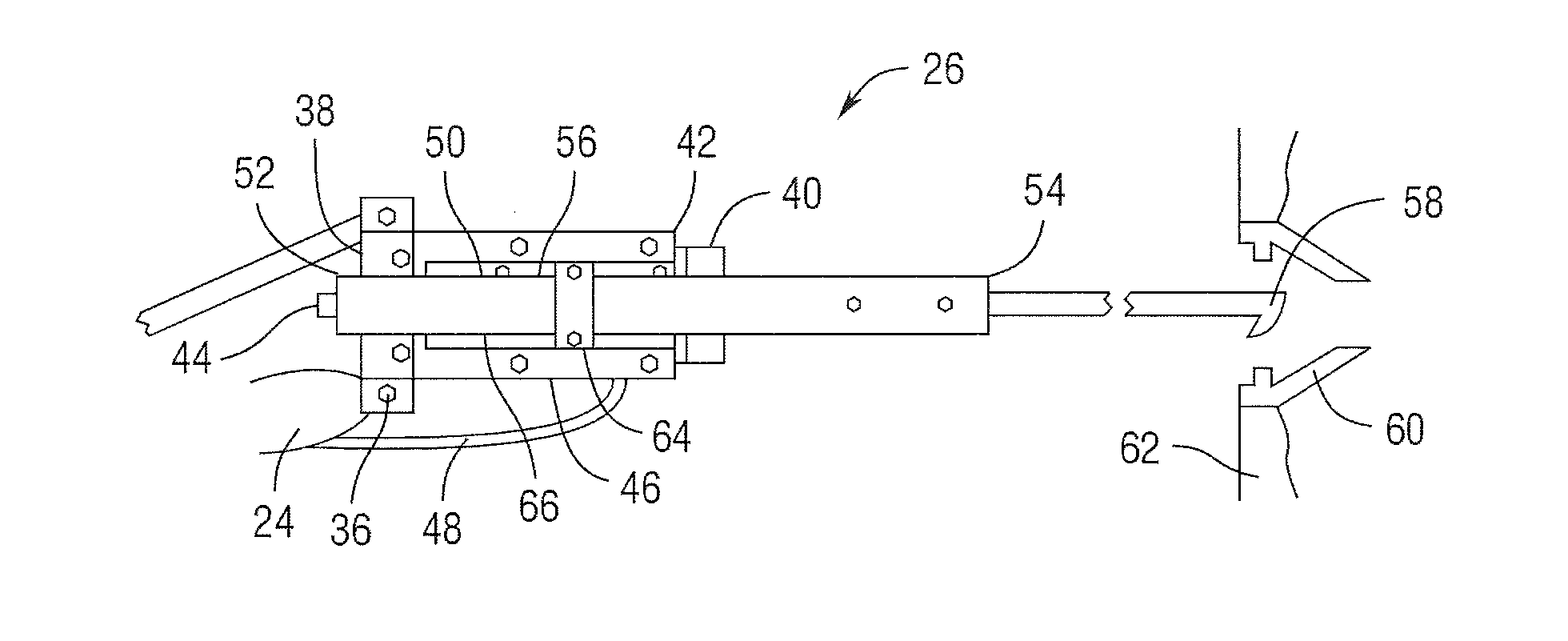
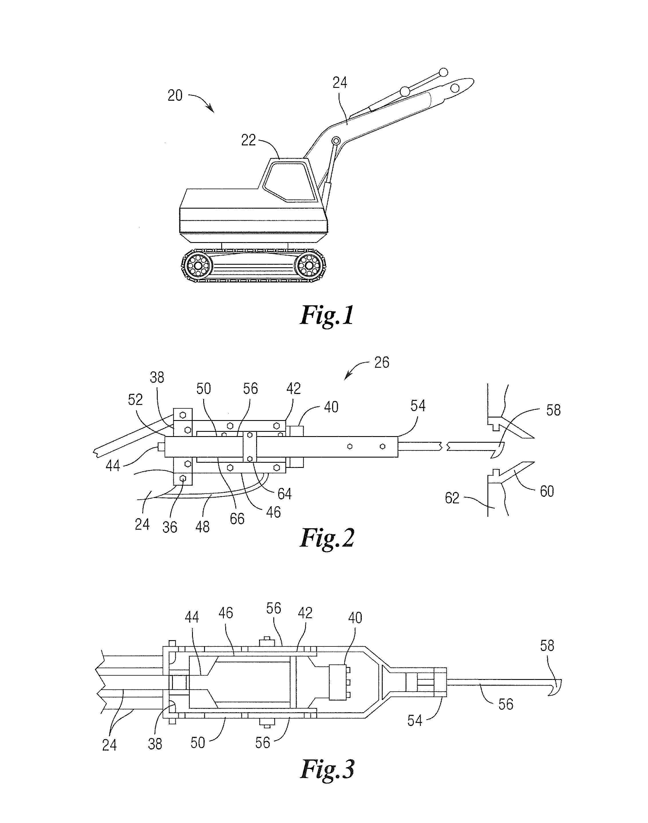
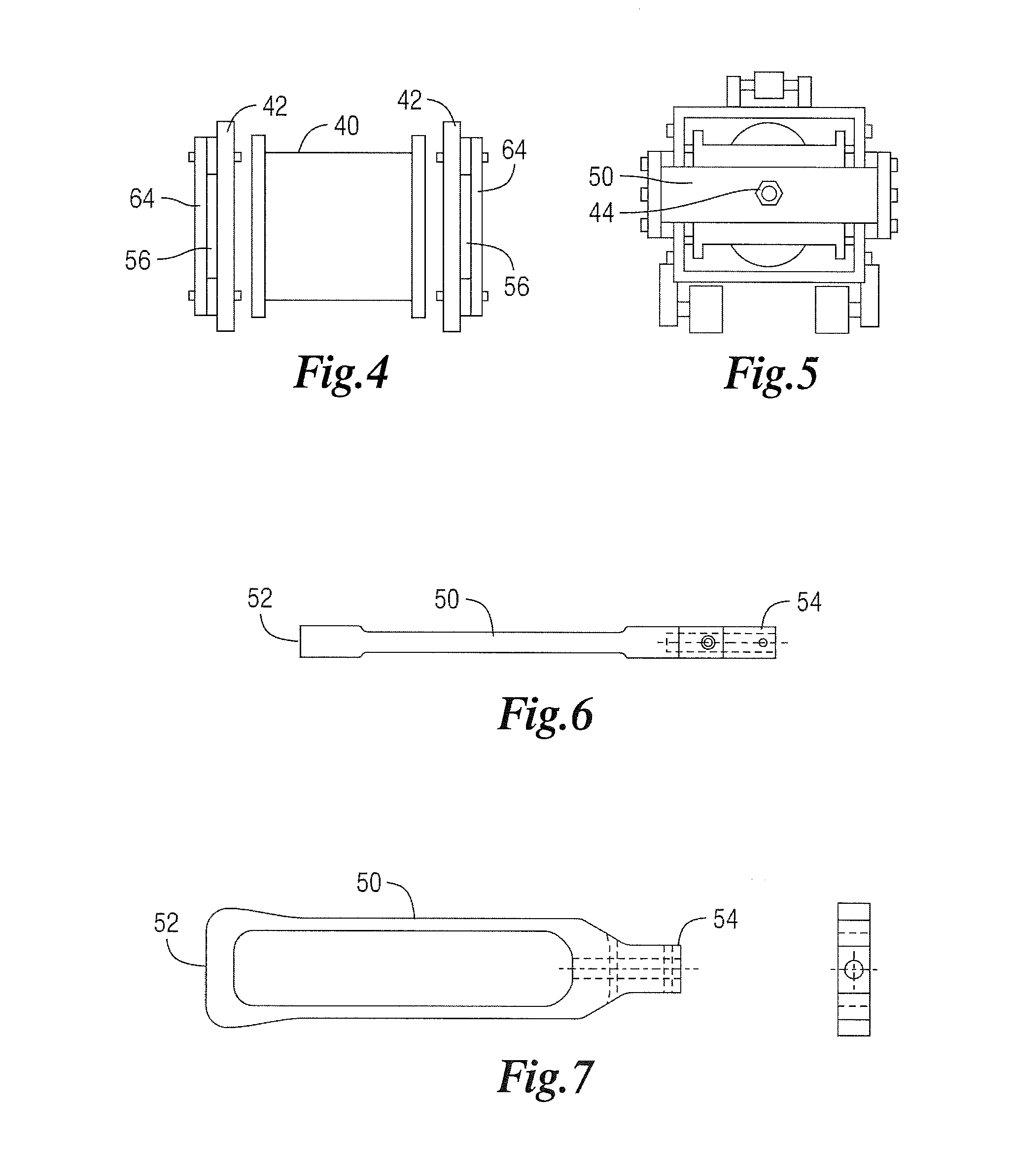
[0022]In the following detailed description, reference is made to the accompanying examples and figures that form a part hereof, and in which is shown, by way of illustration, specific embodiments in which the inventive subject matter may be practiced. These embodiments are described in sufficient detail to enable those skilled in the art to practice them, and it is to be understood that other embodiments may be utilized and that structural or logical changes may be made without departing from the scope of the inventive subject matter. Such embodiments of the inventive subject matter may be referred to, individually and / or collectively, herein by the term “invention” merely for convenience and without intending to voluntarily limit the scope of this application to any single invention or inventive concept if more than one is in fact disclosed. The following description is, therefore, not to be taken in a limited sense, and the scope of the inventive subject matter is defined by the ...


PUM

PropertyMeasurementUnit
timeaaaaaaaaaa
lengthaaaaaaaaaa
pressureaaaaaaaaaa

Abstract

A component of a gas injection system (tuyere / tymp) removal apparatus comprising a pneumatic or hydraulic hammer reverse mounted into a hammer frame, the working end of the hammer fixedly attached a first end of a slidable frame. The slidable frame having a second end fixedly attached to an elongated lifting arm means with a component handling means, and two sides slidably attached to the hammer frame. The component handling means may be inserted into the rear of a component of a gas injection system. When activated, the hammer generates a pulling motion on the component handling means engaged with the component of a gas injection system, releasing the component of a gas injection system from the wall of the blast furnace.

Description

CROSS REFERENCE TO RELATED APPLICATIONS[0001]The present application claims benefit and priority from U.S. provisional application Ser. No. 61 / 499,874 entitled “TUYERE REMOVER”, filed Jun. 22, 2011, the disclosure of which is hereby incorporated by reference herein in its entirety for all purposes.TECHNICAL FIELD OF THE INVENTION[0002]The present invention relates in general to removal devices for components of a gas injection system, and has more particular reference to removal of a tuyere from blast furnace walls by aid of a reverse mounted hydraulic or pneumatic hammer to provide a pulling motion on the tuyere.BACKGROUNDField of the Disclosure[0003]Steel makers are increasingly shaped by the forces of globalization. Increasingly, steel companies are turning to maintenance and service companies to help them develop solutions that will reduce furnace downtimes, reduce costs and improve on mill safety. Many of their maintenance systems are manual, time consuming and have an unaccept...

Claims


Application Information

Patent Timeline
Patent Type & Authority Applications(United States)
IPC IPC(8): C21B7/16
CPCC21B7/166
Inventor PENNEY, JAMES DOUGLAS
Owner TMS INT CORP
Why Eureka
Try Eureka