Sandwich coupling mechanism

a coupling mechanism and sandwich technology, applied in the direction of hose connection, roof drainage, wing accessories, etc., can solve the problems of deformation, failure, deformation, and even catastrophic failure of the edge of the downspout and the downspout extension, and achieve the effect of easy rotation

Active Publication Date: 2013-06-27
GPI HOME SOLUTIONS INC
View PDF35 Cites 10 Cited by
  • Summary
  • Abstract
  • Description
  • Claims
  • Application Information

AI Technical Summary

Benefits of technology

[0009]A brace is disclosed that can securely couple to the edge of a downspout or a downspout extension or even allow a downspout extension to be connected to a downspout. In certain embodiments, the brace comprises a pivot joint that allows the downspout to be easily rotated from a relatively horizontal position to a relatively vertical position in which people can access the areas where the downspout extension. Various hinge embodiments are described herein. For example, in some embodiments, the hinge includes a first plate positioned on the inner wall surface of a downspout and a second plate positioned on an opposing outer wall surface of the downspout. The wall is secured to the hinge and reinforced as a fastener is extended though the first plate, the downspout wall, and the second plate.

Problems solved by technology

However, oftentimes, the edge of downspouts and downspout extensions are unsupported and subject to failure.
A hinged coupler exerts additional forces on the unsupported edge of the downspout and downspout hinge that can lead to deformation and even catastrophic failure.

Method used


Image

  • Sandwich coupling mechanism
  • Sandwich coupling mechanism
  • Sandwich coupling mechanism

Examples


Embodiment Construction

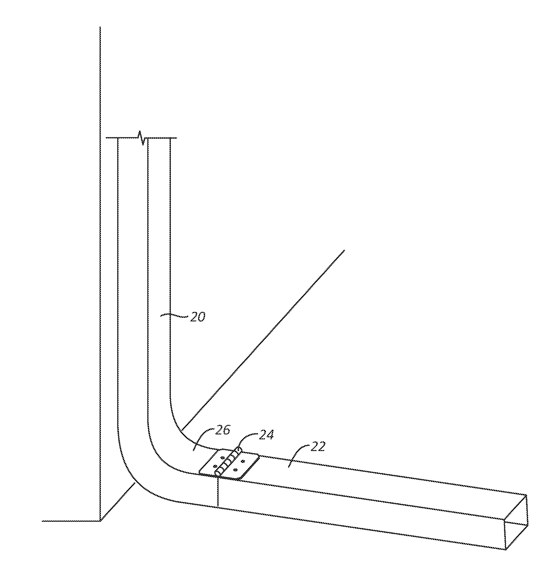
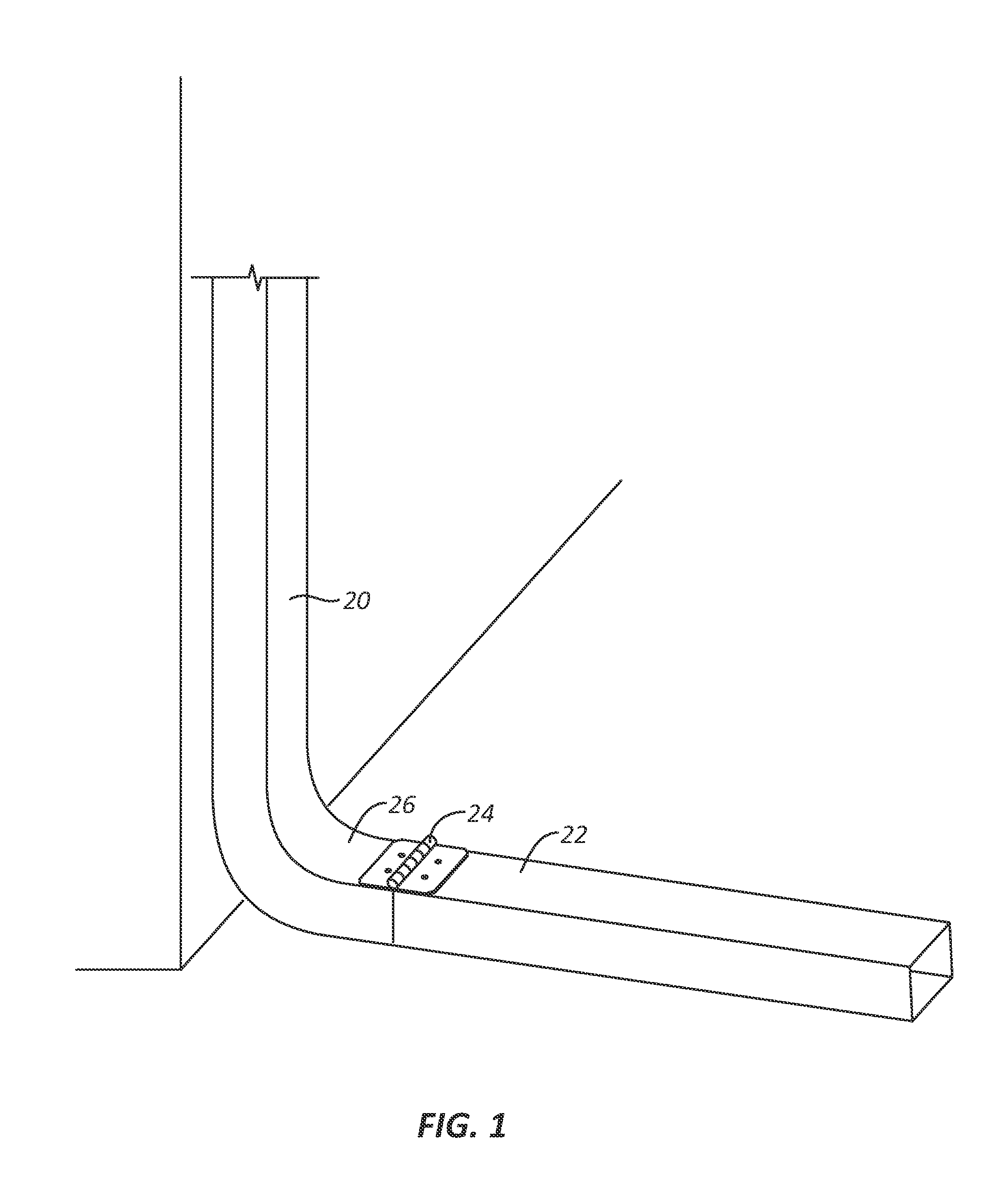
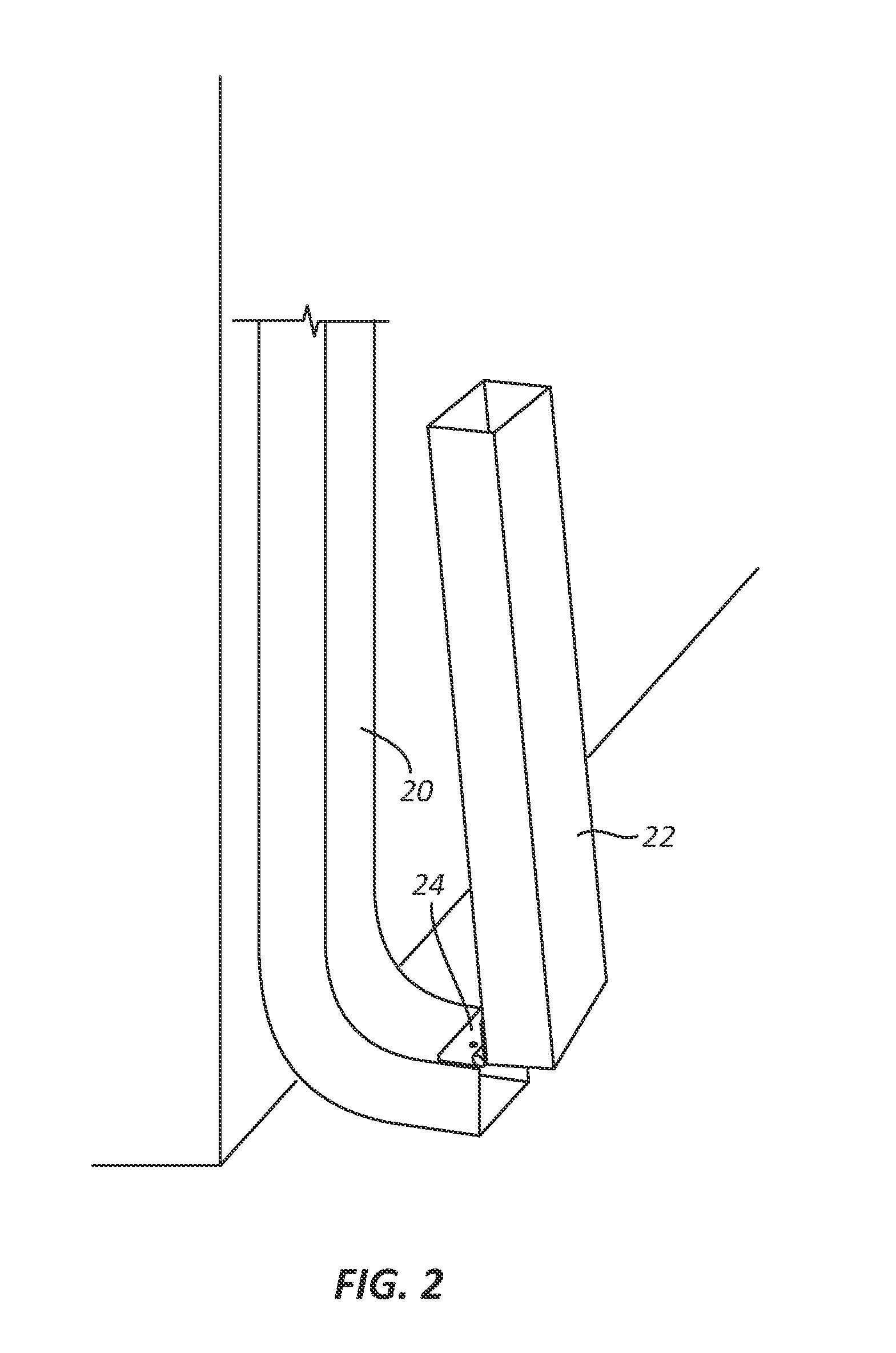
[0036]A description of embodiments of the present invention will now be given with reference to the Figures. It is expected that the present invention may be embodied in other specific forms without departing from its spirit or essential characteristics. The described embodiments are to be considered in all respects only as illustrative and not restrictive. The scope of the invention is, therefore, indicated by the appended claims rather than by the foregoing description. All changes that come within the meaning and range of equivalency of the claims are to be embraced within their scope.

[0037]Numerical data may be expressed or presented herein in a range format. It is to be understood that such a range format is used merely for convenience and brevity and thus should be interpreted flexibly to include not only the numerical values explicitly recited as the limits of the range, but also as including all the individual numerical values or sub-ranges encompassed within that range as i...


PUM


Abstract

A sandwich mechanism is disclosed that has to opposing members that form a pocket into which material such as downspout sheet metal can be inserted. The opposing members clamp onto the downspout and can be secured into place using a screw that passes through the opposing members and the inserted downspout. Two sandwich mechanisms may be coupled together using a brace or a hinged member. The hinged member will permit a user to independently articulate the coupled pieces of downspout or downspout extension.

Description

RELATED APPLICATIONS[0001]This application is a Continuation-in-Part of U.S. patent application Ser. No. 13 / 367,343, filed Feb. 6, 2012, which claims priority to Provisional Patent Application No. 61 / 502,801, filed Jun. 29, 2011.BACKGROUND[0002]1. Background of the Invention and Related Art[0003]Downspouts are often used to control water flow coming off of roofs. Downspouts distribute water onto the ground and potentially away from the foundation of a building by use of extensions that take the water from the downspout to a distance away from a foundation of a building. However, oftentimes, the edge of downspouts and downspout extensions are unsupported and subject to failure. This is especially true when the coupler between the downspout and the downspout extension is hinged. A hinged coupler exerts additional forces on the unsupported edge of the downspout and downspout hinge that can lead to deformation and even catastrophic failure.[0004]2. Summary and Objects of the Invention[0...

Claims


Application Information

Patent Timeline
Patent Type & Authority Applications(United States)
IPC IPC(8): E04D13/08
CPCE04D13/08E05D5/0215E05Y2600/40E05Y2900/60E05D5/04E05D5/127E05D2005/102E05Y2800/21E05Y2800/29E05Y2800/45E05Y2800/00E05D5/06
Inventor BAILEY, LANCE D.
Owner GPI HOME SOLUTIONS INC
Why Eureka
Try Eureka