LED light- emitting device and indicator provided with the LED light emitting device

a technology of led light emitting device and indicator, which is applied in the direction of lighting and heating apparatus, light source combinations, instruments, etc., can solve the problems of low color rendering properties, which become important in normal illumination, and achieve high distinguishability

Inactive Publication Date: 2013-06-27
CMC MAGNETICS CORPORATION
View PDF4 Cites 21 Cited by
  • Summary
  • Abstract
  • Description
  • Claims
  • Application Information

AI Technical Summary

Benefits of technology

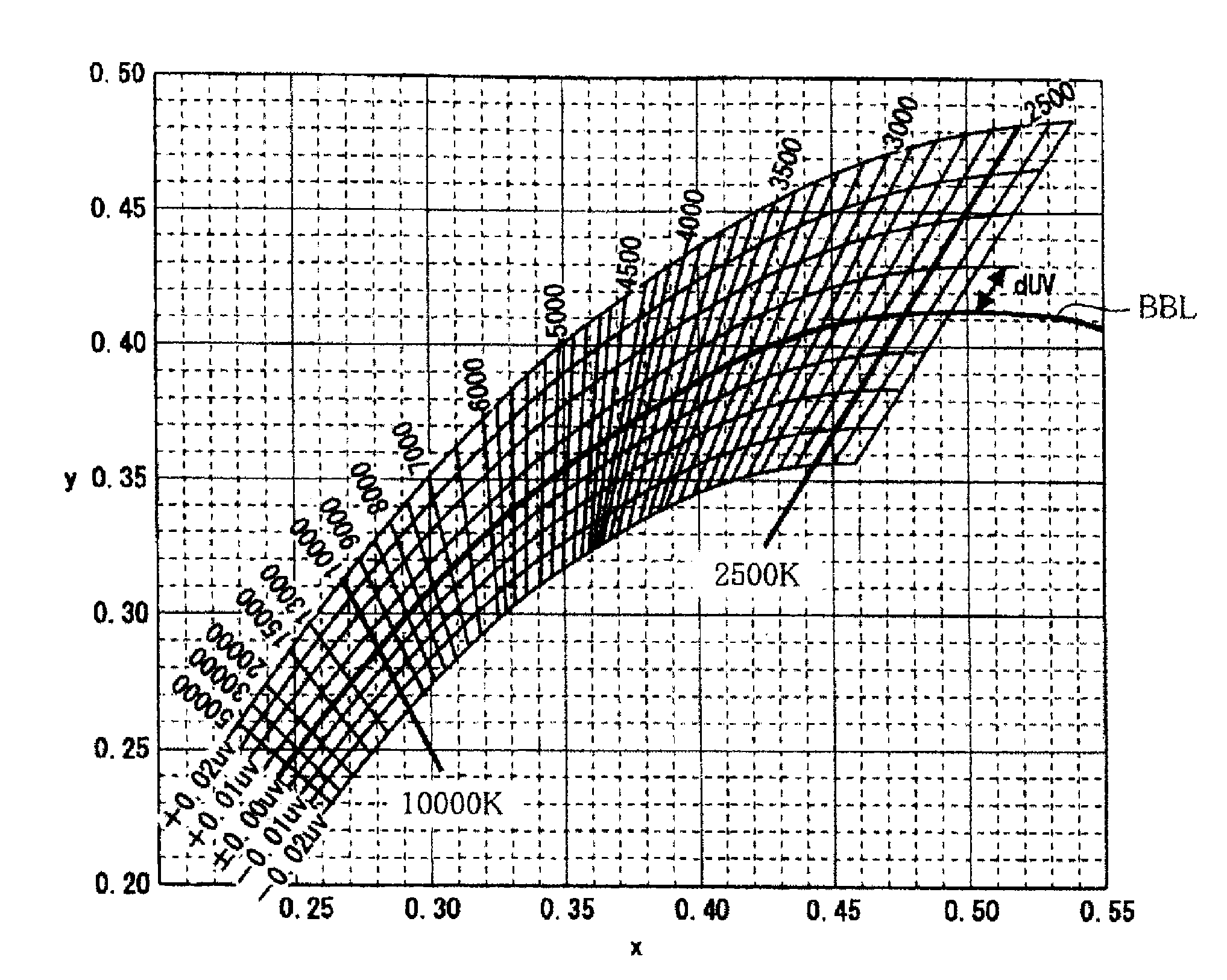
[0036]According to the LED light emitting device of the present invention, the drive controller unit controls the first drive current to be supplied to the first LED and the second drive current to be supplied to the second LED, respectively, whereby the chromaticity of a combined light obtainable by variously changing the ratio of the respective visible lights from the first and second LEDs, changes within the changeable range of chromaticity where the color difference is larger than 0.04 in the CIE (1976) L*u*v* color space chromaticity diagram, and thus can be made to be one which is different in a clearly distinguishable level from the emission color of the first LED and the emission color of the second LED. Furthermore, in an intermediate region within this changeable range of chromaticity, a white light is obtainable as a combined light, of which the absolute value of a deviation duv from the blackbody radiation locus is at most 0.02 in the CIE (1976) L*u*v* color space chromaticity diagram and the color temperature is within a range of from 2,500 K to 10,000 K, and thus it becomes possible to realize a distinct change of the emission color and at the same time, a highly distinguishable white light can be obtained even in an intermediate region within the changeable range of the emission color.
[0037]Further, in a case where such a drive controller unit of the LED light emitting device is designed to control the first and second drive currents so that the chromaticity of a combined light moves on a line that connects the chromaticity of the emission color of the first LED and the chromaticity of the emission color of the second LED, the drive controller unit may be made to be simply constructed.
[0038]In such a case, when it is so designed that the line that connects the chromaticity of the emission color of the first LED and the chromaticity of the emission color of the second LED, passes through a chromaticity point where X is at least 0.32 and at most 0.34, and Y is at least 0.32 and at most 0.34 in the CIE (1931) XYZ color space, it becomes possible to have a white color of daylight color radiated from the LED light emitting device in an intermediate region within the changeable range of the emission color, whereby the distinguishability can further be increased.
[0039]In a case where the emission color of the first LED and the emission color of the second LED are in a complementary color relation to each other, the above-mentioned effect such that it becomes possible to realize a distinct change of the emission color over the entire region within the changeable range of the emission color of the LED light emitting device, becomes more distinct. Here, as mentioned above, “in a complementary color relation to each other” means that they are in a point symmetrical relation about the 0 point in the CIE 1976 (L*a*b*) color space, but is not limited to a strict point symmetrical relation. Specifically, in a case where on the a*b* coordinate plane represented by the CIE 1976 (L*a*b*) color space, a color phase is represented by an angle θa* of a line segment OC connecting the 0 point (a*=0, b*=0) and color point C, from the a* axis, it is preferred that a difference between the respective angles θa* of color points of the two emission colors is at least 120° and at most 240°. That is, the emission color of the first LED and the emission color of the second LED are preferably such that on the a*b* coordinate plane in the CIE (1976) L*a*b* color space chromaticity diagram, the angle between a line segment that connects the origin and coordinates representing the emission color of the first LED and a line segment that connects the origin and coordinates representing the emission color of the second LED, is an angle of at least 120° and at most 240°. By such a construction, even in a case where the emission color of the first LED and the emission color of the second LED are not strictly in a point symmetrical relation on the a*b* coordinate plane in the CIE (1976) L*a*b* color space chromaticity diagram, a white color is radiated in the course of change from the emission color of the first LED 301 to the emission color of the second LED 302, and it is possible to realize a distinct change of the emission color. Since the emission color of the first LED 301 and the emission color of the second LED 302 are not required to be strictly in a point symmetrical relation on the a*b* coordinate plane in the CIE (1976) L*a*b* color space chromaticity diagram, it is possible to flexibly determine the emission color of the first LED 301 and the emission color of the second LED 302.
[0040]The emission color of the first LED 301 and the emission color of the second LED 302 may be such that on the a*b* coordinate plane in the CIE (1976) L*a*b* color space chromaticity diagram, the difference between the length of a line segment that connects the origin and coordinates representing the emission color of the first LED 301 and the length of a line segment that connects the origin and coordinates representing the emission color of the second LED 302, is less than 20. Further, the emission color of the first LED 301 and the emission color of the second LED 302 may be such that on the a*b* coordinate plane in the CIE (1976) L*a*b* color space chromaticity diagram, as between the length of a line segment that connects the origin and coordinates representing the emission color of the first LED 301 and the length of a line segment that connects the origin and coordinates representing the emission color of the second LED 302, the ratio of one of them to the other and the ratio of the other to said one of them are at most 2.0. By such a construction, in the course of change from the emission color of the first LED 301 to the emission color of the second LED 302 or in the course of change from the emission color of the second LED 302 to the emission color of the first LED 301, a white light can be radiated in an intermediate region. Therefore, in a case where an LED light emitting device having such a construction is applied for indication of a physical quantity, for example, when the physical quantity is minimum, such a state is indicated by the emission color of the first LED 301, when the physical quantity is maximum, such a state is indicated by the emission color of the second LED 302, and when the physical quantity is at an intermediate level, such a state is indicated by a white color, and thus, the change of the physical quantity can easily be recognized.
[0041]The emission color of the first LED 301 and the emission color of the second LED 302 may be such that on the a*b* coordinate plane in the CIE (1976) L*a*b* color space chromaticity diagram, the length of a line segment that connects the origin and coordinates representing the emission color of the first LED 301 and the length of a line segment that connects the origin and coordinates representing the emission color of the second LED 302, are, respectively, at least 5. By such a construction, the emission color of the first LED 301 and the emission color of the second LED 302 are different from a white color, and in the course of change from the emission color of the first LED 301 to the emission color of the second LED 302, it is possible to make the change of the color of light emitted from the LED light emitting device more certainly recognizable. Further, the construction may be such that on the a*b* coordinate plane in the CIE (1976) L*a*b* color space chromaticity diagram, the coordinates representing the emission color of the first LED are characterized in that the value of a* is smaller than −20 and the value of b* is smaller than 20, and the coordinates representing the emission color of the second LED are characterized in that the value of a* is larger than 20 and the value of b* is larger than −20. By such a construction, from the first LED, a light with a color capable of giving an impression of “safe”, “normal”, “cold”, “cool” or the like, is usually emitted, and from the second LED, a light with a color capable of giving an impression of “danger”, “abnormal”, “warm”, “hot” or the like, is usually emitted. That is, the impression to be given by the light emitted from the first LED may be made to be in contrast with the impression to be given by the light emitted from the second LED. Thus, the impression to be given to the observer of the light emitted from the LED light emitting device can be changed to a contrasting impression.

Problems solved by technology

In nature, a semiconductor light emitting element itself has a relatively narrow emission spectrum width, and if light emitted from such a semiconductor light emitting element itself is used for illumination as it is, there may be a problem that color rendering properties which become important in usual illumination, tend to be low.

Method used


Image

  • LED light- emitting device and indicator provided with the LED light emitting device
  • LED light- emitting device and indicator provided with the LED light emitting device
  • LED light- emitting device and indicator provided with the LED light emitting device

Examples


application example 1

[0129]FIG. 10 is a configuration diagram schematically showing Application Example 1 wherein the LED light emitting device 1 of the present invention is applied to an indicator 150 of a temperature-setting dial (operation member) 140 for an air conditioner (electronic device) 100 to be used for e.g. a vehicle. The temperature-setting dial 140 is rotatable in a range from the lower limit position shown by the indication “LOW” to the upper limit position shown by the indication “HIGH”. On the top surface of the temperature-setting dial 140, an indicator 150 formed in a ring shape is provided, and for illumination of this indicator 150, radiation light of the LED light emitting device 1 of the present invention is used. That is, the temperature-setting dial 140 corresponds to the operation member 40 in the above-described embodiment, and the indicator 150 corresponds to the indicator 50. Accordingly, in this application example, the physical quantity to be set by using the temperature-...

application example 2

[0134]In the foregoing embodiment and Application Example 1, it is so designed that the indication controller section 51 controls the drive controller section 32 depending upon the position of the operation member 40 or the temperature-setting dial 140, however, it may be designed so that the indication color of the indicator is changed depending upon the degree of the physical quantity which is variously changed depending upon e.g. surroundings instead of the physical quantity to be artificially set by e.g. the operation member 40 or the temperature-setting dial 140. In such a case, a sensor (not shown) to detect the objective physical quantity, is used instead of the operation member 40 or the temperature-setting dial 140. An example for application to such an indicator will be described below as Application Example 2.

[0135]FIG. 11 is a configuration diagram schematically showing an example wherein the LED light emitting device 1 of the present invention is applied to an indicator...


PUM


Abstract

A first LED emits visible light of an emission color such that with respect to a CIE(1976)L*u*v* color space chromaticity diagram, the chromaticity is exterior to a prescribed white light region wherein the absolute value of a deviation duv from the blackbody radiation locus is at most 0.02 and the color temperature is within a range of from 2,500K to 10,000K, and the deviation duv from the blackbody radiation locus is larger than 0.02, and a second LED emits visible light of an emission color such that with respect to the above chromaticity diagram, the chromaticity is exterior to the prescribed white light region, and the deviation duv from the blackbody radiation locus is smaller than −0.02.

Description

TECHNICAL FIELD[0001]The present invention relates to an LED light emitting device employing LEDs, and an indicator employing light emitted from such an LED light emitting device to carry out an indication.BACKGROUND ART[0002]LED light emitting devices employing LEDs have been widely used as light sources for various illumination and display devices. Further, an LED light emitting device has also been developed and used, wherein plural types of LEDs that emit different colors from semiconductor light emitting elements such as LED chips, are used in combination so that the respective emission colors are combined to obtain a desired radiation color. For example, Patent Document 1 discloses an LED light emitting device wherein three types of LEDs that emit e.g. blue light, green light and red light, are used in combination, and drive currents to be supplied to the respective LEDs are adjusted, so that the lights emitted from the respective LEDs are combined to obtain a desired white li...

Claims


Application Information

Patent Timeline
Patent Type & Authority Applications(United States)
IPC IPC(8): H05B33/08B60Q3/00H05B44/00
CPCF21Y2113/005G01D11/28H01L25/0753H01L33/50H01L33/60H01L2924/09701H05B33/0803H01L2224/73265H05B33/0872H05B33/0857B60Q3/001H01L2224/48091H01L2924/00014F21Y2115/10F21Y2113/13B60Q3/85H05B45/00H05B45/20H05B45/30H01L2924/0002H01L2924/00
Inventor SHAMOTO, TAKESHIKASAUKURA, AKEOTAKEDA, TORU
Owner CMC MAGNETICS CORPORATION
Why Eureka
Try Eureka