Single Inductor Multiple Output Power Converter

a power converter and single inductor technology, applied in the direction of electric variable regulation, process and machine control, instruments, etc., can solve the problems of capacitor occupying precious board space, difficult to find effective means of modulating current in the inductor, and further complicated, and achieve excellent regulation and minimal cross regulation

Active Publication Date: 2013-06-27
QUALCOMM INC
View PDF12 Cites 11 Cited by
  • Summary
  • Abstract
  • Description
  • Claims
  • Application Information

AI Technical Summary

Benefits of technology

[0026]It is an objective of the present invention to provide a single inductor multiple output power converter that achieves minimum cross regulation between its outputs in any load condition and load mismatch. ...

Problems solved by technology

If and when the loads are very dissimilar it is quite difficult to find effective means to modulate the current in the inductor in synchronism with the multiplexing of the output switches.
This is further complicated by the fact that the multiplexing ...

Method used


Image

  • Single Inductor Multiple Output Power Converter
  • Single Inductor Multiple Output Power Converter
  • Single Inductor Multiple Output Power Converter

Examples


Embodiment Construction
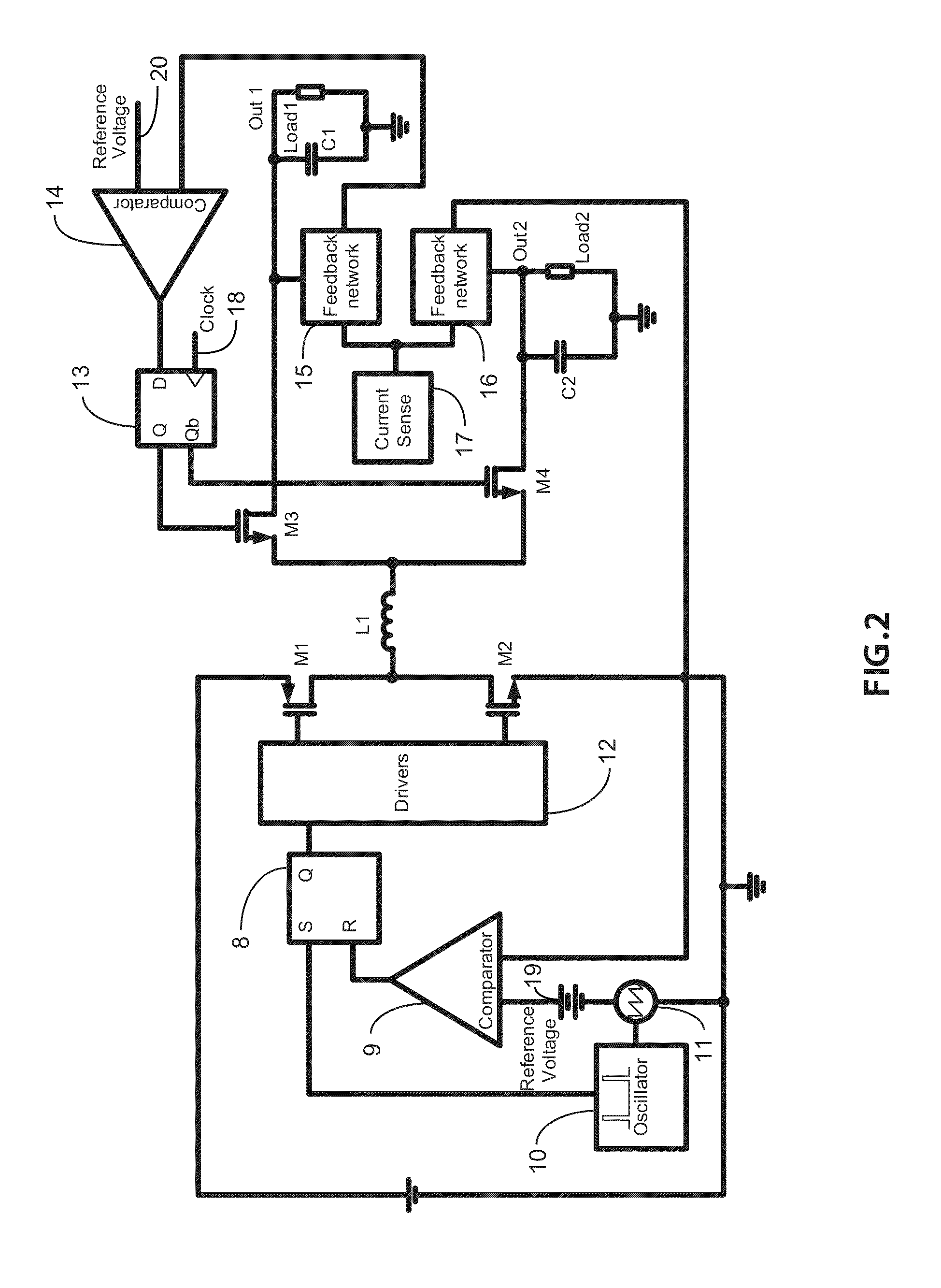
A FIG. 2

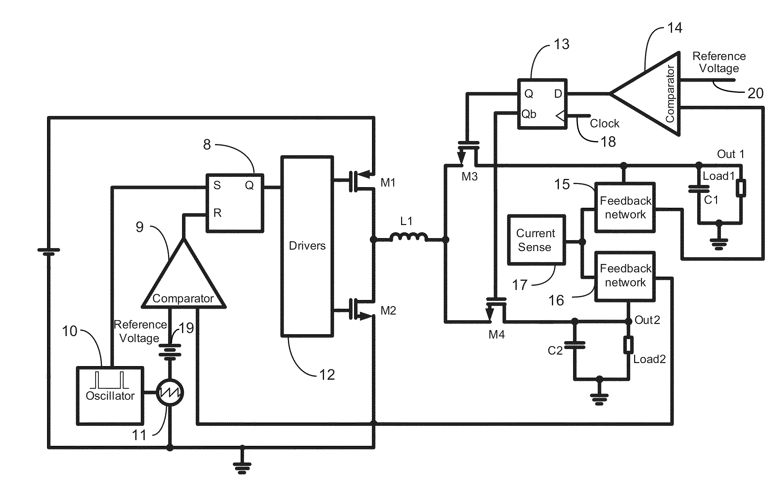
[0080]The circuit, as depicted in FIG. 2, shows a single inductor dual output step down power converter, but similar considerations can be extended to multiple output power converters with more than two outputs. The power converter of FIG. 2 shows two main loops: the first one to control the duty cycle of the power devices M1 and M2 and the second loop to control the switching of the power devices M3 and M4. The power converter of FIG. 2 employs a minimum off-time type of control operating at constant frequency featuring the feedback network 16 that generates the synthetic ripple signal, but similar considerations can be made for a hysteretic type of control with a switching frequency control circuitry (PLL).

[0081]The synthetic ripple signal is a signal replica of the output voltage ripple but it is amplified to make it more immune to switching noise. Typically the feedback network 16 is constituted of passive elements but it could include transistors as well. The block diag...


PUM


Abstract

A novel method to operate and control single inductor multiple output switching power converter is presented. The method includes the means for generating one or more synthetic ripple signals and operating the converter at constant switching frequency allowing high frequency operation, maintaining stability in all conditions with minimum cross regulation between the outputs independently on the levels of load present at the outputs. The method further includes means for setting the maximum frequency of multiplexing the energy stored in the inductor between the various outputs reaching the desired compromise between the value of the output capacitors, the switching frequency of the output power devices and the acceptable output voltage ripple.
Two different topologies are proposed that can be used for single inductor multiple output buck power converters and for boost power converter allowing the extension to buck-boost configurations as well.

Description

BACKGROUND OF THE INVENTION[0001]1. Field of the Invention[0002]The present invention is in the field of power converters. The present invention is further in the field of semiconductor switching power converters. The present invention further relates to the field of integrated synthetic ripple control methods for switching power converters and circuits. The present invention is further in the field of integrated switching power converters. The present invention is further in the field of hysteretic control types for switching power converters. The present invention is further in the field of single inductor multiple output switching power converters. The implementation is not limited to a specific technology, and applies to either the invention as an individual component or to inclusion of the present invention within larger systems which may be combined into larger integrated circuits.[0003]2. Brief Description of Related Art[0004]Modern electronic applications require power manag...

Claims


Application Information

Patent Timeline
IPC IPC(8): G05F1/577
CPCY02B70/16H02M3/158H02M2001/009H02M2001/0032H02M2001/0025H02M1/0025H02M1/0032H02M1/009Y02B70/10
Inventor MENEGOLI, PAOLOMARINO, FABIO ALESSIO
Owner QUALCOMM INC
Why Eureka
Try Eureka