Image registration method and system robust to noise

a technology of image registration and noise, applied in the field of digital image processing, can solve problems such as methods failing, and achieve the effect of improving image registration methods and systems

Active Publication Date: 2013-06-27
ECOLE DE TECH SUPERIEURE
View PDF0 Cites 34 Cited by
  • Summary
  • Abstract
  • Description
  • Claims
  • Application Information

AI Technical Summary

Benefits of technology

[0047]The Image Evaluation module is configured to perform the visual quality assessment by any of: determining a peak signal-to-noise ratio (PSNR); computing a structural similarity (SSIM) index; and computing visual information fidelity (VIF) index.
[0048]Thus, improved image registration methods and systems have been provided.

Problems solved by technology

700-703, 1987 who have developed an image registration method for translated and rotated images using finite Fourier transforms, but this method fails in the presence of scale change; a paper by W. Wei, S. Wang, X. Zhang and Z. Tang, “Estimation of image rotation angle using interpolation-related spectral signatures with application to blind detection of image forgery,” IEEE Transactions on Information Forensics and Security, vol.

Method used


Image

  • Image registration method and system robust to noise
  • Image registration method and system robust to noise
  • Image registration method and system robust to noise

Examples


first embodiment

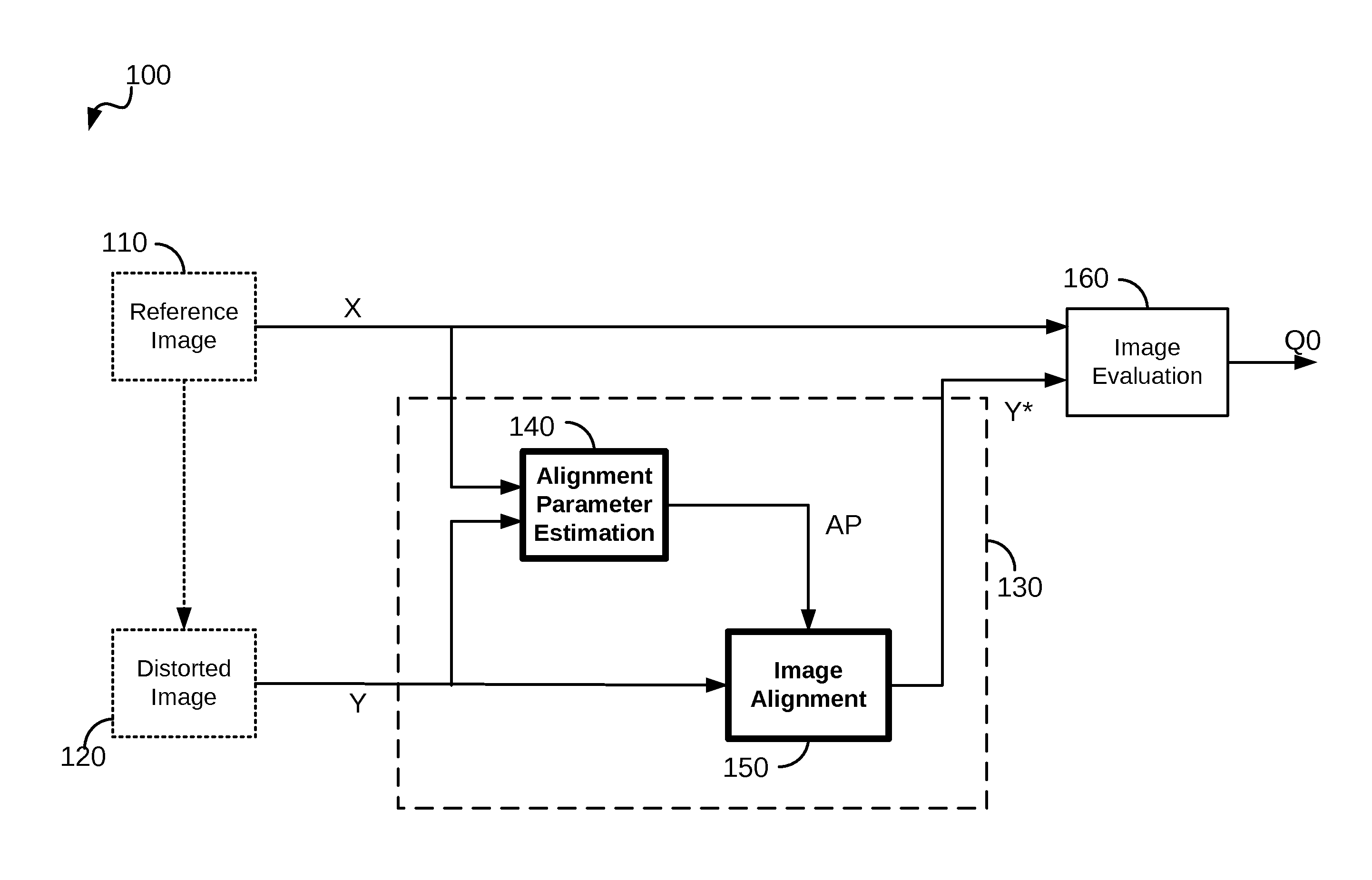
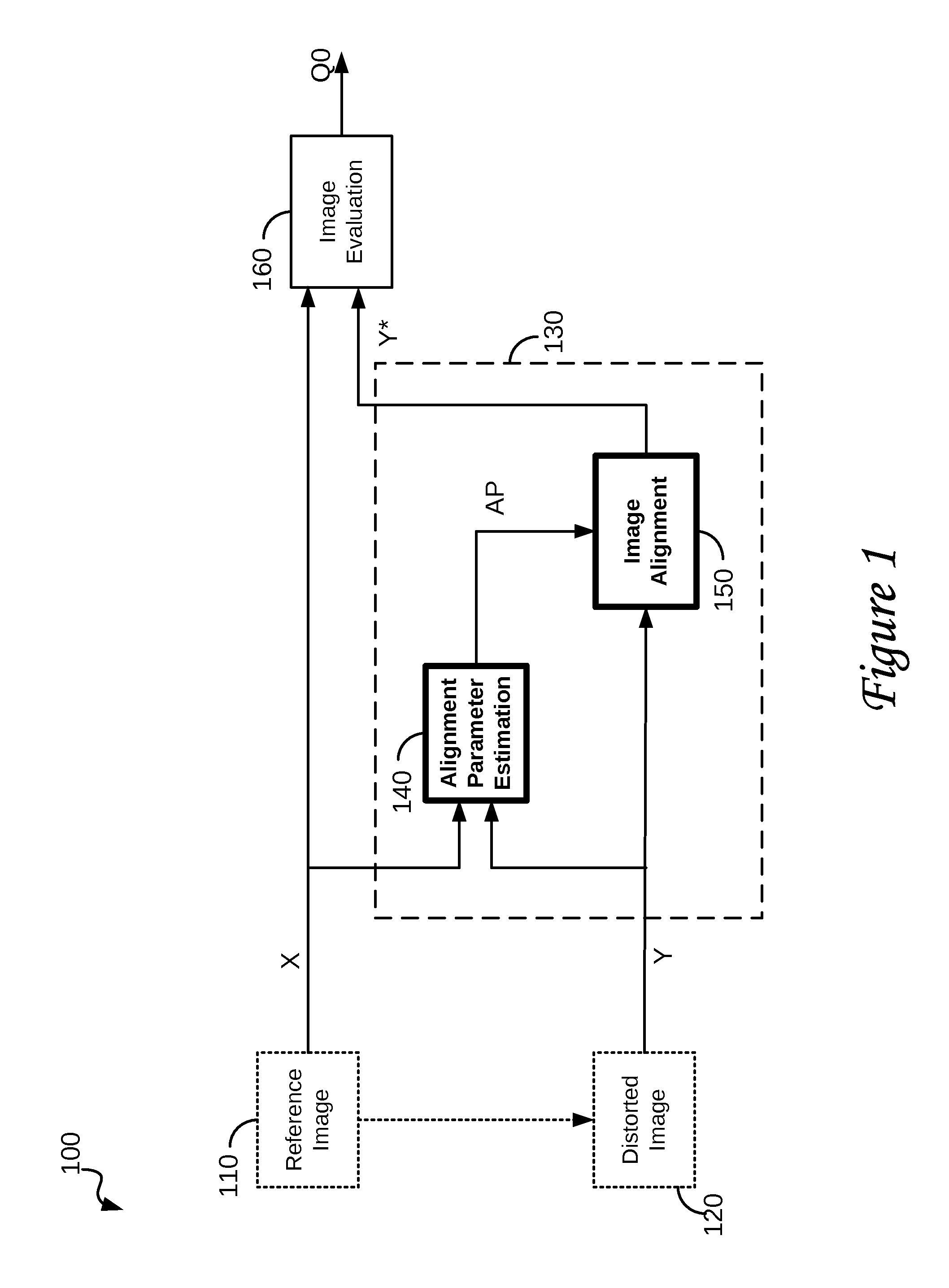
[0126]the Image Pre-processing system 130 is based on:[0127]extracting sets of keypoints from both the Reference Image X and the Distorted Image Y;[0128]matching a selected number of pairs of keypoints from X and Y that are closest;[0129]solving for parameters of a first affine transform;[0130]generating a second affine transform which is an inverse of the first affine transform;[0131]applying the second affine transform on the Distorted Image Y, thereby generating the Pre-processed Image Y*.

[0132]A keypoint is known as a Scale Invariant Feature Transform (SIFT) parameter set that was proposed by D. G. Lowe in “Distinctive Image Features from Scale-Invariant Keypoints,” International Journal of Computer Vision, vol. 60, no. 2, pp. 91-110, 2004, to characterize a distinctive area in an image. Two specific implementations of the Alignment Parameter Estimation process 140 and corresponding implementations of the Image Alignment process 150 are proposed.

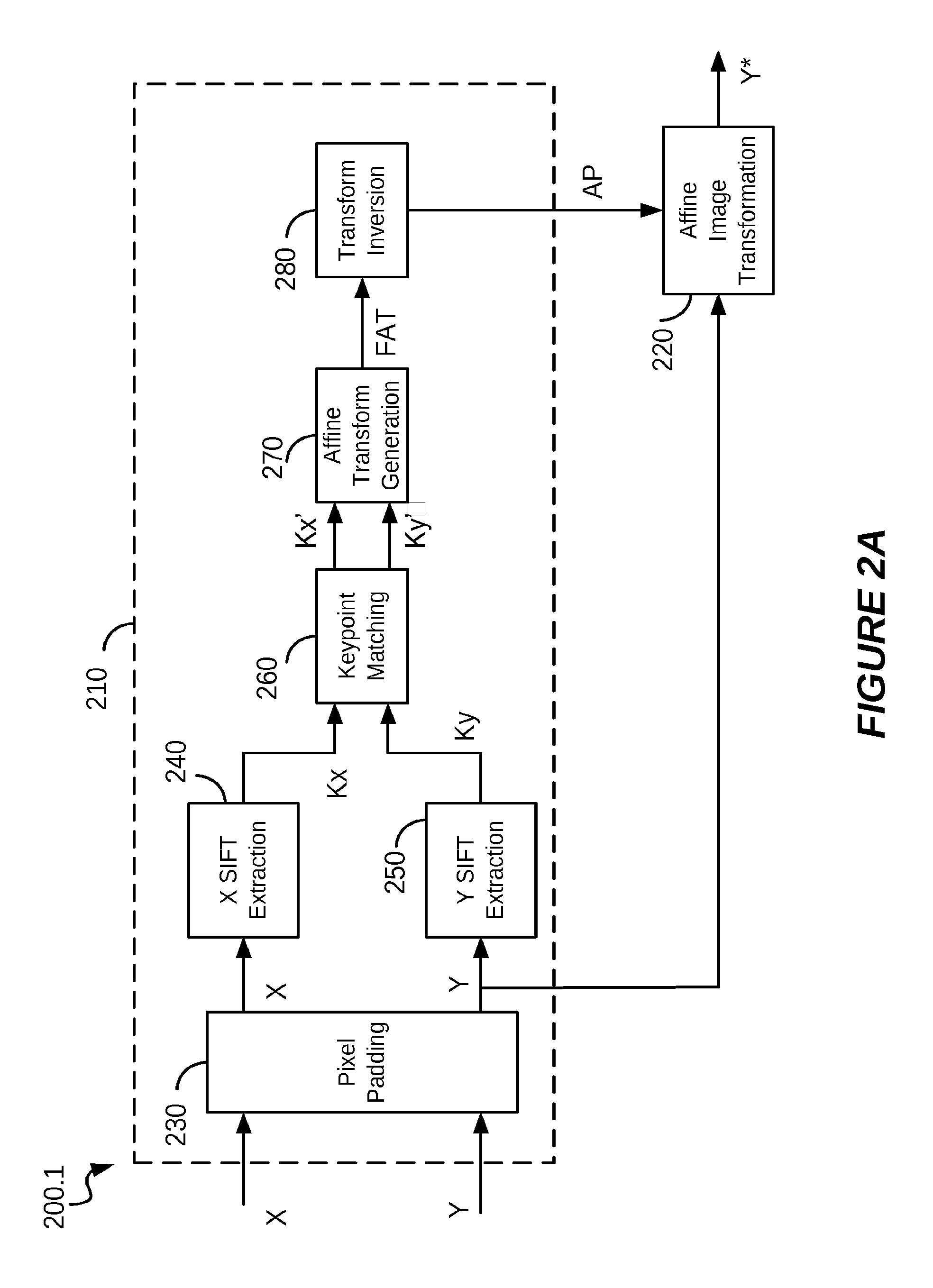
[0133]FIG. 2a shows a block diagr...

second embodiment

[0141]FIG. 2b shows a block diagram of an alternative Affine Transform based image alignment system 200.2 which is the Image Pre-processing system 130. The alternative Affine Transform based image alignment system 200.2 of FIG. 2b provides the same functionality as the Affine Transform based image alignment system 200.1 of FIG. 2a, with the exception that the Transform Inversion module 280 and the Affine Image Transformation module 220 are combined into a single, more efficient, Affine Compensated Image Generation module 290.

[0142]FIG. 3 is a flow chart of an affine transform based realignment method 300 according to the first embodiment of the invention, including steps:[0143]310“Zero Pad Image(s)”;[0144]320“Extract Key Features”;[0145]330“Match Keypoints”;[0146]340“Number of Matching Pixels[0147]350“Estimate Affine Parameters”;[0148]360“Invert Transform”;[0149]370“Perform Affine Transform”;[0150]380“Generate Affine Compensated Image”; and[0151]390“Fill Blank Pixels”.

[0152]Let the ...

third embodiment

[0206]FIG. 15 is a block diagram of a first Radon Transform based image alignment system 1500 which is the Image Pre-processing system 130 of FIG. 1, comprising the following modules:

a Scaling Factor Estimation module 1502 for determining the scale factor “a”;

an Image Masking module 1504 for extracting a masked image Y0 from the Distorted Image Y;

a Centroid Computation module 1506 for determining centering parameters “cr” and “cc” from the masked image Y0;

an Image Centering module 1508 for centering the Distorted Image Y and generate a centered image Y1 using the centering parameters “cr” and “cc”;

and

an Image Resizing module 1510 for resizing the centered image Y1 into a resized Distorted Image Y2 using the scale factor “a”.

[0207]The resized Distorted Image Y2 is of the same size as the Reference Image X and has been centered, but may still need to be rotated.

[0208]The first Radon Transform based image alignment system 1500 further includes:

a Rotation Angle Determination unit 1511 c...


PUM


Abstract

An image registration method is disclosed for processing a distorted image into a registered image that is aligned with reference to an original image. Distortions from the original image may include scaling, rotation, and noise. The method is based on correlating Radon transforms of both images to determine the rotation angle, and the scaling factor is determined by dividing averages of the overall luminance of each image on the assumption that any added noise will cancel. The Fast Fourier Transform (FFT) is used to estimate global spatial shifts. In one embodiment, the distorted image is first scaled to the size of the original image before being rotated. In another embodiment, the original image is first scaled to the size of the distorted image before rotating the distorted image, and finally scaling it to match the original image. A corresponding system for image registration is also provided.

Description

RELATED APPLICATIONS[0001]The present application claims priority from U.S. provisional applications Ser. Nos. 61 / 580,200 filed on Dec. 24, 2011 and 61 / 603,347 filed on Feb. 26, 2012, entire contents of which are incorporated herein by reference.FIELD OF THE INVENTION[0002]The present invention generally relates to digital image processing, specifically to processing an image in combination with a reference image.[0003]The present invention relates to image registration, including estimating translation, rotation, and scaling parameters between a reference image and a distorted image. In particular, the present invention relates to the image registration system and method robust to noise.[0004]The present invention relates to the assessment of a visual quality of an image, and particular to a method and system for assessment of a visual quality of an image that are robust to affine transforms.BACKGROUND OF THE INVENTION[0005]Image registration is an important task in applications su...

Claims


Application Information

Patent Timeline
Patent Type & Authority Applications(United States)
IPC IPC(8): G06T3/00
CPCG06T7/0036G06T3/0068G06T7/37
Inventor CHEN, GUANGYICOULOMBE, STEPHANE
Owner ECOLE DE TECH SUPERIEURE
Why Eureka
Try Eureka