Fixation clamp with thumbwheel

a technology of fixing clamps and thumbwheels, applied in the field of fixing clamps, can solve the problems of pins or rods, bulky fixing systems, and many users' mention of the clamping process in some occasions, and achieve the effect of facilitating the clamping process

Active Publication Date: 2013-06-27
STRYKER EURO OPERATIONS HLDG LLC
View PDF7 Cites 2 Cited by
  • Summary
  • Abstract
  • Description
  • Claims
  • Application Information

AI Technical Summary

Benefits of technology

[0010]It is an aspect of the present invention to provide a fixation clamp which provides an easier clamping process, in particular the fixation clamp shall be pre-tensioned manually or hand-operated respectively, and tensioned by means of a tool, such as a wrench.
[0011]Such an aspect is solved by the features of claim 1. Accordingly a fixation clamp, more particularly for use in an external fixation system for holding bone fragments adjacent to each other with the help of fixation elements, comprises at least one clamping assembly having at least one reception to accommodate a fixation element along the longitudinal axis of the reception and at least one locking element extending through the clamping assembly which locking element provides a clamping force to clamp the fixation element upon tensioning the locking element. The fixation clamp comprises an actuation element which is in connection with the locking element such that the locking element is actuateable by means of the actuation element, and the actuation element is designed such that it is detachable from the locking element after use and that remounting onto the locking element is prevented after having detached the actuation element from the locking element.
[0014]Preferably the actuation element is provided with at least one latching element which engages with the locking element. Alternatively the actuation element comprises at least two or at least three latching elements which are arranged diagonally with respect to the locking element from each other. Thereby the latching elements are arranged such that it is not possible to spread the latching element by means of a tool such as a screwdriver which means that with such a configuration the risk that the user remounts the actuation element becomes even smaller.

Problems solved by technology

U.S. Patent Application Publication No. 2006 / 0287652 mentions that usual fixation clamps as e.g. known from U.S. Pat. No. 6,080,153 allow clamping of one single screw or pin to the frame and that this way to attach pins or rods leads to bulky fixation systems.
Although the users such as surgeons provide very good feedback concerning the handling of such a fixation clamp, many of the users mentioned clamping process in some occasions is difficult.
Furthermore the fixation clamps as known from prior art have the drawback that the user is not able to recognize, if the fixation clamp has been sterilized or if it was already used.

Method used


Image

  • Fixation clamp with thumbwheel
  • Fixation clamp with thumbwheel
  • Fixation clamp with thumbwheel

Examples


Embodiment Construction

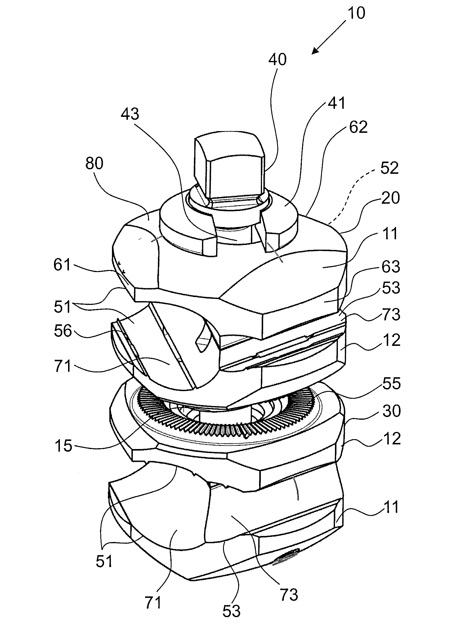
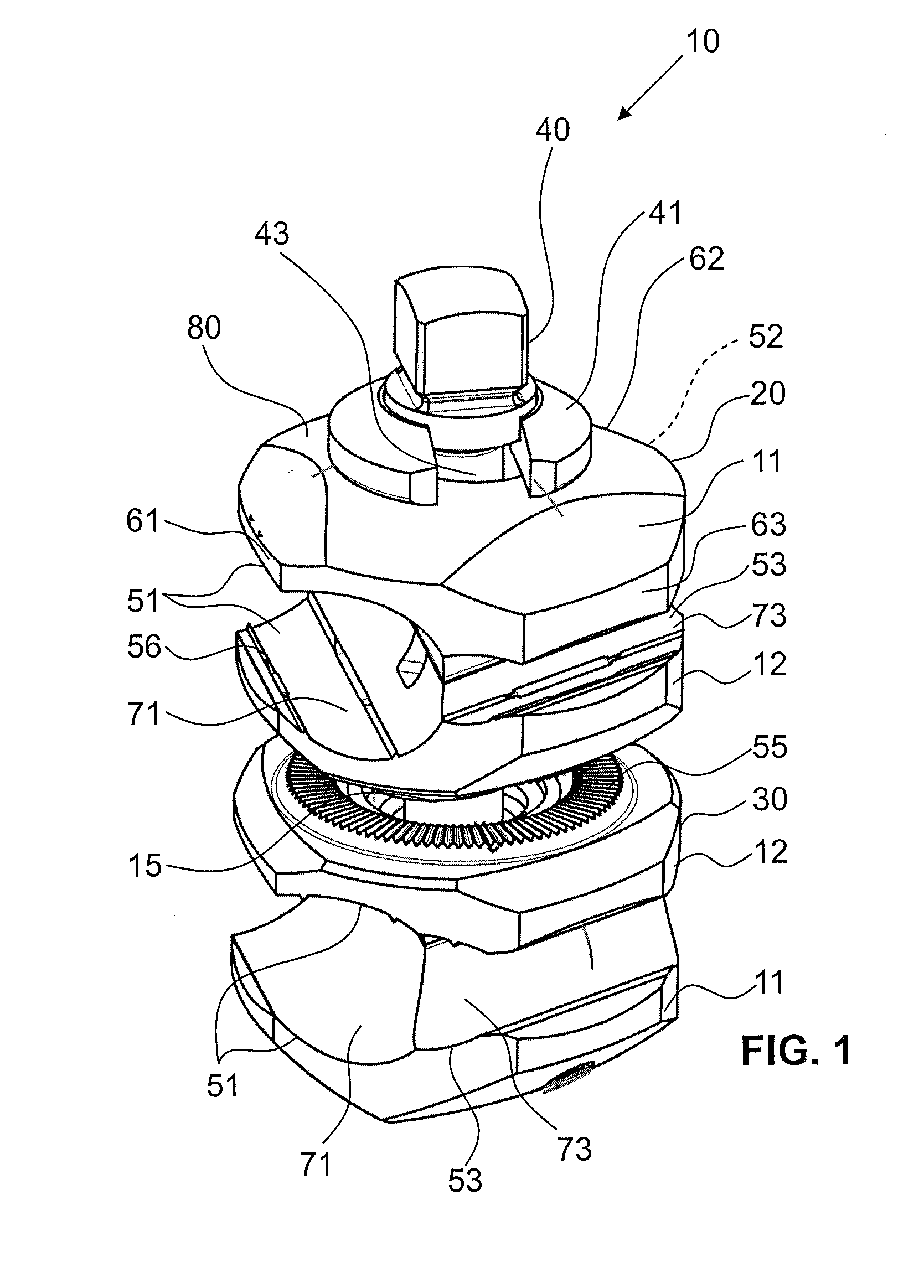
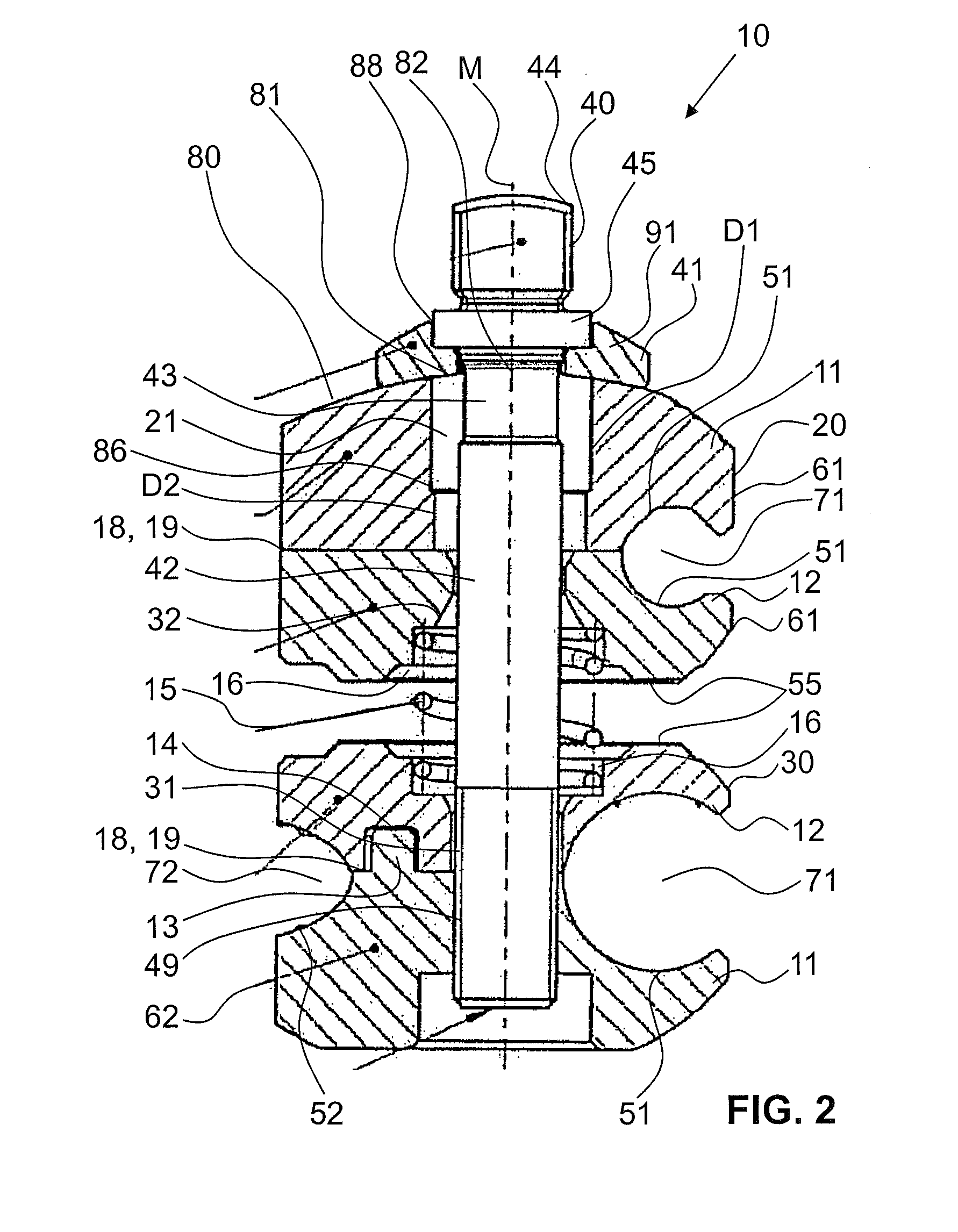
[0028]FIGS. 1 and 2 show a preferred first embodiment of a clamping element or fixation clamp 10 pursuant to the invention. The clamping element 10 consists of a first clamping assembly 20 and a second clamping assembly 30 and a locking element or shaft 40 which is positioned through bores 21, 31 within the two clamp assemblies 20, 30 along the longitudinal axis M of shaft 40. The shaft 40 is preferably a locking element adapted to allow closing the clamp assemblies 20 and 30. Shaft 40 enters a first jaw 11 through a washer 41.

[0029]The shaft 40 comprises a head portion 44, a reduced diameter portion 43 which is followed by a shaft portion 42 and a thread portion 49. The outer threaded portion 49 is adapted to be screwed into a complementary inner thread within the distal jaw 11 so that turning the head of the shaft 40 changes the longitudinal position of the shaft 40 against the lower jaw 11, which allows opening or closing the entire clamp 10 against the force of a spring 15 provi...


PUM


Abstract

A fixation clamp, more particularly for use in an external fixation system for holding bone fragments adjacent to each other with the help of fixation elements, has at least one clamping assembly having at least one reception opening to accommodate a fixation element along the longitudinal axis of the reception opening. At least one locking element extends through the clamping assembly which locking element provides a clamping force to clamp the fixation element upon tensioning the locking element. The fixation clamp further comprises an actuation element which is in connection with the locking element such that the locking element is actuateable by means of the actuation element, and the actuation element is designed such that it is detachable from the locking element after use and that remounting onto the locking element is prevented after having detached the actuation element from the locking element.

Description

CROSS-REFERENCE TO RELATED APPLICATIONS[0001]The present application is a continuation of U.S. patent application Ser. No. 13 / 302,619, filed on Nov. 22, 2011 which claims priority from European Patent Application No. 10 194 944.4 filed Dec. 14, 2010, the disclosures of which are hereby incorporated herein by reference.BACKGROUND OF THE INVENTION[0002]The present invention relates to a fixation clamp and, more particularly, to a fixation clamp for use in an external fixation system for holding bone fragments adjacent to each other.[0003]External fixation systems are widely used to connect two or more bone fragments to each other. Such systems comprise bone screws, pins, wires which are inserted directly into the bone material and these systems use external structural elements as fixation rods, bars and rings. In order to connect the rods and bars to form a rigid frame, fixation clamps are used. Furthermore, fixation clamps are used to connect this screws and pins to the rigid frame t...

Claims


Application Information

Patent Timeline
Patent Type & Authority Applications(United States)
IPC IPC(8): A61B17/60
CPCA61B17/6416A61B17/645A61B17/6458A61B17/6466A61B17/60A61B17/888A61B2017/0023A61B2019/4873A61B17/8615A61B2090/0814
Inventor DOMINIK, ROBERTBUSCH, ADAMDORAWA, KLAUS
Owner STRYKER EURO OPERATIONS HLDG LLC
Why Eureka
Try Eureka