Autonomous mobile body

a mobile body and autonomous technology, applied in the direction of process and machine control, distance measurement, instruments, etc., can solve the problem of taking more time to reach the destination

Active Publication Date: 2013-06-27
MURATA MASCH LTD
View PDF23 Cites 52 Cited by
  • Summary
  • Abstract
  • Description
  • Claims
  • Application Information

AI Technical Summary

Benefits of technology

[0006]Thus, preferred embodiments of the present invention provide an autonomous mobile body that appropriately performs a stopping action or a retreat action according to circumstances when there is an obstacle that may interfere with the autonomous mobile body.
[0008]With the foregoing autonomous mobile body according to the present invention, the storage means stores a size of the autonomous mobile body in a horizontal direction, and the width identification means identifies a passage width showing a size, in a width direction, of a passage which is a region where the planned path is set and the autonomous mobile body can move. Moreover, the obstacle information acquisition means acquires obstacle information of obstacles around the autonomous mobile body, and, based on the obstacle information, the calculation means calculates a size of an obstacle existing in a moving target direction with respect to a direction which is substantially perpendicular to the moving target direction of the autonomous mobile body on a plane which is parallel to a passage plane. In other words, the size of an obstacle that may be an interference with if the autonomous mobile body continues to move forward is calculated. In addition, the selection means selects a stopping action or a retreat action based on the size of the autonomous mobile body, the obstacle size, and the passage width. In other words, the autonomous mobile body selects either the stopping action or the retreat action based on information which is required for determining whether it is a situation where the autonomous mobile body and the obstacle can pass each other on the passage. In addition, the mobile control means controls the autonomous mobile body to stop when the stopping action is selected, and controls the autonomous mobile body to retreat when the retreat action is selected. Accordingly, the autonomous mobile body can appropriately perform a stopping action or a retreat action according to circumstances when there is an obstacle that may be an interference with.
[0022]According to the foregoing preferred configuration, the autonomous mobile body independently sets the standby position on the retreat path which intersects with the passage upon selecting the retreat action, and retreats toward the set standby position. Consequently, under circumstances where the autonomous mobile body and the obstacle cannot pass each other on the passage, it is possible to create a situation where the obstacle can pass through on the passage by the autonomous mobile body retreating from the passage.
[0024]According to the foregoing preferred configuration, under circumstances where the autonomous mobile body and the obstacle cannot pass each other on the passage, it is possible to create a situation where the obstacle can pass through on the passage by the autonomous mobile body retreating from the passage, and, after standing by for a predetermined time at the standby position, the autonomous mobile body resumes travel along the original planned path. Accordingly, if the obstacle is a person or the like which can move autonomously, once the obstacle passes through the passage, the autonomous mobile body can return to the passage and once again resume its travel along the planned path.
[0031]According to the present invention, it is possible to appropriately perform a stopping action or a retreat action according to circumstances when there is an obstacle that may interfere with the autonomous mobile body.

Problems solved by technology

Nevertheless, in the foregoing case, if the autonomous mobile body retreats even in cases where the autonomous mobile body and the obstacle can pass each other within the passage, it will take more time to reach the destination.

Method used


Image

  • Autonomous mobile body
  • Autonomous mobile body
  • Autonomous mobile body

Examples


Embodiment Construction

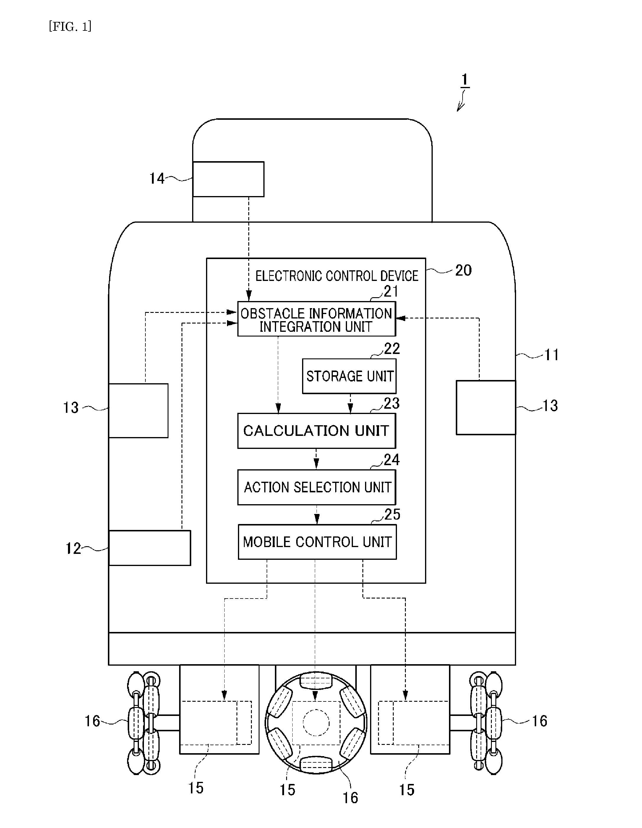
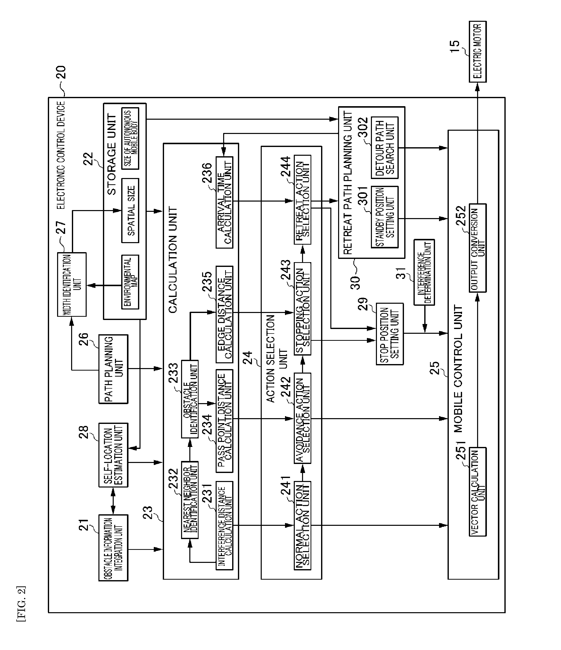
[0060]The preferred embodiments of the present invention will now be explained in detail with reference to the drawings. The outline of the autonomous mobile body 1 according to a preferred embodiment of the present invention is foremost explained with reference to FIG. 1. FIG. 1 is a diagram showing the schematic configuration of the autonomous mobile body 1.

[0061]The autonomous mobile body 1 according to this preferred embodiment is, for example, a robot which is deployed in facilities such as a hospital or a factory, and independently plans the path to the destination and autonomously moves along the planned path while avoiding obstacles such as walls and pillars. Note that the autonomous mobile body according to various preferred embodiments of the present invention can also be applied to an AGV (Automated Guided Vehicle) or the like. The autonomous mobile body 1 plans the path so as to avoid the known obstacles stored in an environmental map in advance, and, upon moving along t...


PUM


Abstract

An autonomous mobile body includes a laser range sensor and an electronic control device. The electronic control device includes a storage unit that stores a size D2 of the autonomous mobile body, a width identification unit that identifies a spatial size D1 in a width direction of a passage which is a region where the autonomous mobile body can move, a calculation unit that calculates a size 8 of an interfering obstacle in a direction which is substantially perpendicular to a moving target direction on a road surface based on obstacle information, an action selection unit that selects a stopping action or a retreat action based on the spatial size D1, the size D2 of the autonomous mobile body, and the size D8 of the interfering obstacle, and a mobile control unit that controls the autonomous mobile body to stop when the stopping action is selected and control the autonomous mobile body to retreat when the retreat action is selected.

Description

BACKGROUND OF THE INVENTION[0001]1. Field of the Invention[0002]The present invention relates to an autonomous mobile body which moves autonomously.[0003]2. Description of the Related Art[0004]Conventionally, an autonomous mobile body which autonomously moves to a destination is known. For example, Japanese Patent Application Publication No. 2009-288930 describes an autonomous mobile body which detects an obstacle using a laser range finder, and autonomously moves while avoiding interference with the detected obstacle. Moreover, Japanese Patent Application Publication No. H9-185412 describes an autonomous mobile body which determines, when an obstacle is detected forward in the traveling direction by an ultrasonic sensor, that the obstacle is a person when there is an output from an infrared sensor. This autonomous mobile body stops when it is determined that the obstacle is a person, and stands by for a given period of time in anticipation of that person getting out of the way.[000...

Claims


Application Information

Patent Timeline
Patent Type & Authority Applications(United States)
IPC IPC(8): G05D1/00
CPCG05D1/024G05D1/0251G05D1/0255G05D1/0088G05D1/0274G05D2201/0206G05D2201/0216G05D1/0272G05D1/0223G05D1/02B60W60/0011
Inventor SHITAMOTO, HIDEONAKANO, TSUYOSHIMORIGUCHI, TOSHIKI
Owner MURATA MASCH LTD
Why Eureka
Try Eureka