Gas pressure regulating valve

a technology of gas pressure regulating valve and valve body, which is applied in the direction of fluid pressure control, process and machine control, instruments, etc., can solve the problems of difficult control operation, narrow span of duty control for changing from a low flow rate to a high flow rate, and difficult pressure control of fuel gas in the low flow rate region (low load state)

Active Publication Date: 2013-07-04
KAWASAKI HEAVY IND LTD
View PDF7 Cites 16 Cited by
  • Summary
  • Abstract
  • Description
  • Claims
  • Application Information

AI Technical Summary

Benefits of technology

[0042]The present invention can provide a gas pressure regulating valve capable of, even under a high-pressure fuel gas circumstance, more precisely regulating secondary pressure of the high-pressure fuel gas to target pressure and preventing a fuel gas from leaking to the atmosphere.

Problems solved by technology

Especially, in a low flow rate region (the fuel cell or the gas engine is in a low load state), a flow gain (a value obtained by dividing the flow rate of the fuel gas by the duty ratio) is large, and the control operation is difficult.
In addition, another problem is that if the upstream pressure of the injector increases, the span of duty control for changing from a low flow rate to a high flow rate becomes extremely narrow.
Therefore, as with the injector, in the electromagnetic pressure regulating valve, the pressure control of the fuel gas in the low flow rate region (low load state) is extremely difficult.

Method used


Image

  • Gas pressure regulating valve
  • Gas pressure regulating valve
  • Gas pressure regulating valve

Examples


embodiment 1

Configuration of Electromagnetic Pressure Regulating Valve

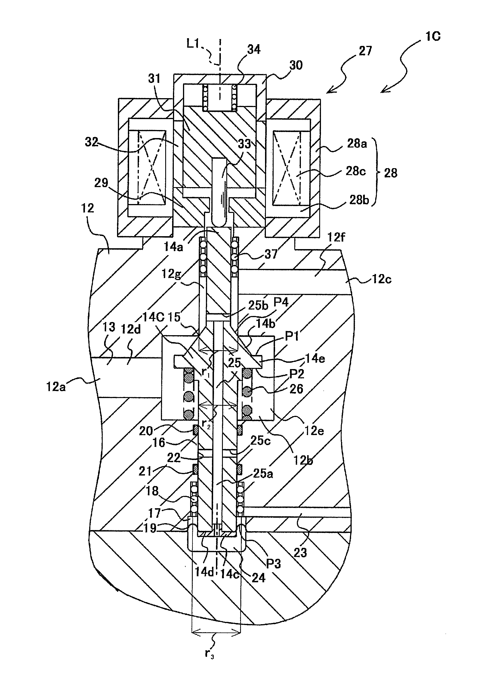
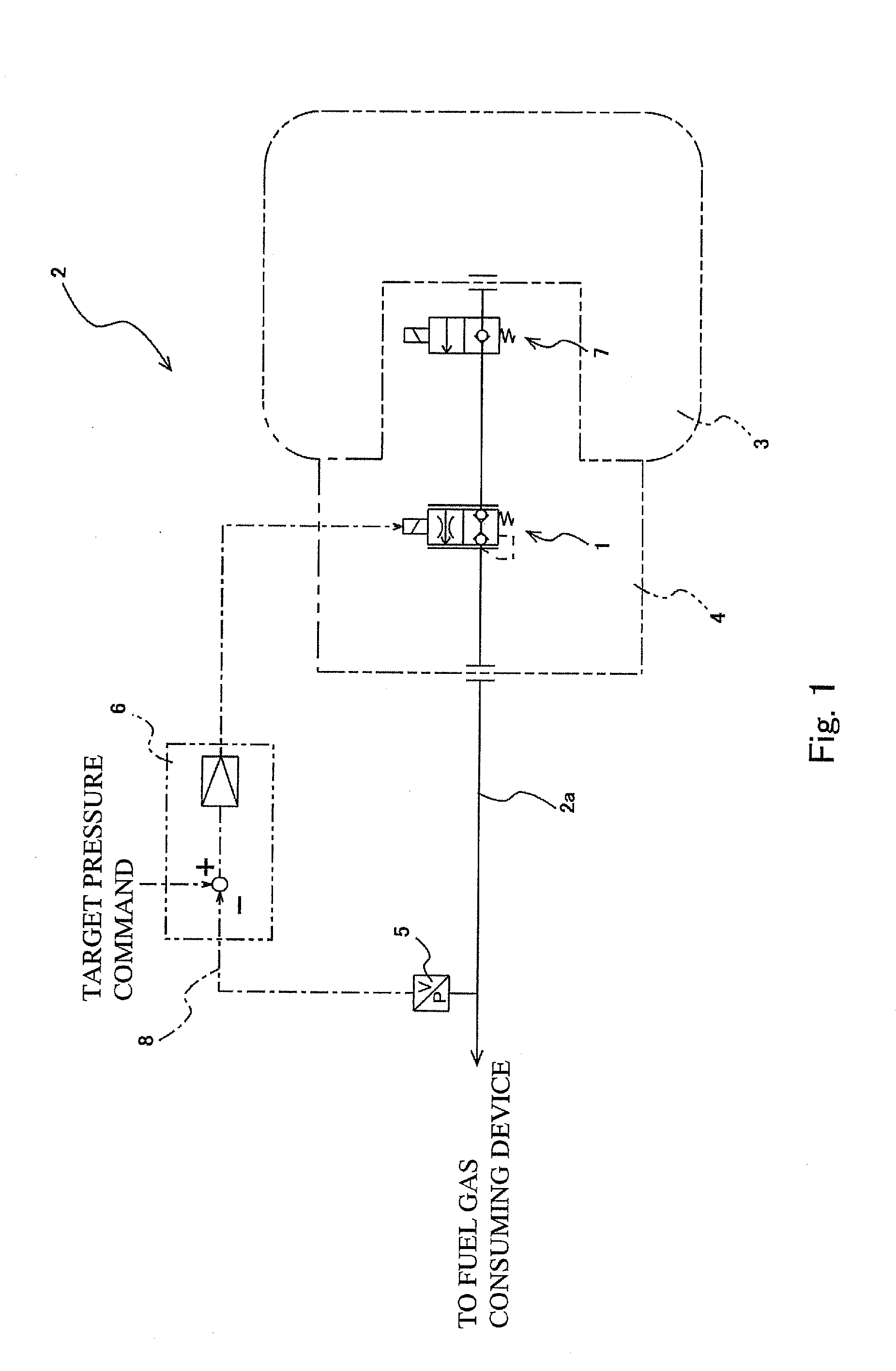
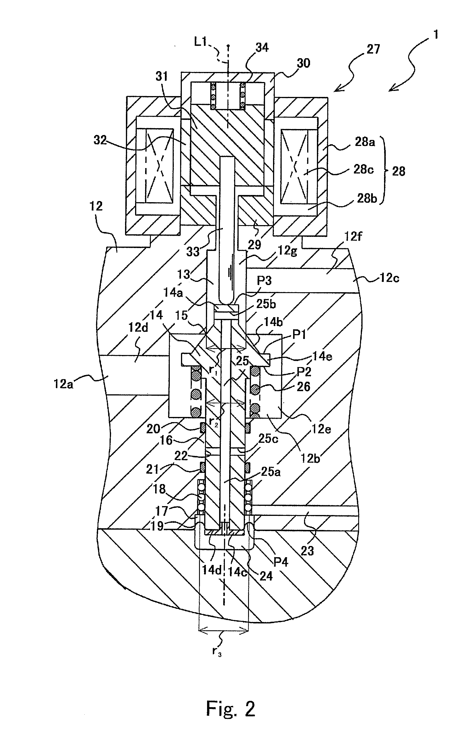
[0071]The electromagnetic pressure regulating valve 1 of Embodiment 1 shown in FIG. 2 includes a housing 12. The housing 12 is attached to an opening portion of the high-pressure tank 3 (see FIG. 1) in a sealed state. The housing 12 includes a primary port 12a, a valve body hole 12b, and a secondary port 12c. The primary port 12a is connected to the electromagnetic shutoff valve 7 (see FIG. 1) and is connected to the valve body hole 12b through a primary passage 12d formed in the housing 12.

[0072]The valve body hole 12b extends along an axis line L1 extending in the upper-lower direction. A lower side of the valve body hole 12b is closed, and an upper side thereof is open. The valve body hole 12b has a circular cross section and includes a valve space 12e at an intermediate portion thereof, the valve space 12e being larger in diameter than the other portion of the valve body hole 12b. The primary passage 12d is connected to t...

embodiment 2

[0098]The electromagnetic pressure regulating valve 1A according to Embodiment 2 of the present invention is similar in configuration to the electromagnetic pressure regulating valve 1 according to Embodiment 1. Herein, only components of the configuration of the electromagnetic pressure regulating valve 1A according to Embodiment 2 different from components of the electromagnetic pressure regulating valve 1 according to Embodiment 1 will be explained. The same reference signs are used for the same components, and explanations thereof are omitted. The same is true for Embodiment 3 and subsequent embodiments.

[0099]As shown in FIG. 3, the electromagnetic pressure regulating valve 1A according to Embodiment 2 of the present invention includes a pressure return passage 35 in a housing 12A. The pressure return passage 35 is formed to connect the secondary passage 12f of the valve passage 13 and the pressure return chamber 24 and introduces the secondary pressure p2 to the pressure return...

embodiment 3

[0101]As shown in FIG. 4, the electromagnetic pressure regulating valve 1B according to Embodiment 3 of the present invention includes a valve body 14B. A circumferential groove 36 which is concave in a radially inward direction is formed on the valve body 14B so as to be located between the high-pressure sealing member 20 and the low-pressure sealing member 21. The circumferential groove 36 is formed on an outer periphery of the valve body 14B along the entire periphery. A buffer chamber 22B is formed by the circumferential groove 36 and an inner peripheral surface of the housing 12B so as to be located between the high-pressure sealing member 20 and the low-pressure sealing member 21.

[0102]A pressure return passage 35B is formed in the housing 12B. The pressure return passage 35B connects the secondary passage 12f and the pressure return chamber 24 and also connects the secondary passage 12f and the buffer chamber 22B. With this, the secondary pressure p2 can be introduced through...


PUM


Abstract

An electromagnetic pressure regulating valve includes a valve body and causes a valve body to move by an electromagnetic proportional solenoid to adjust an opening degree of a valve passage, thereby regulating secondary pressure to target pressure. A pressure return chamber is formed in the housing, and a diaphragm seal is provided at the valve body. The diaphragm seal receives the secondary pressure of the pressure return chamber to cause the valve body to move toward a closed position. A bearing member is provided between the valve body and the housing. In a gap between the valve body and the housing, a high-pressure sealing member is provided closer to the valve passage than the bearing member, and a low-pressure sealing member is provided closer to the bearing member than the high-pressure sealing member. A buffer chamber connected to a secondary port is formed between the sealing members.

Description

TECHNICAL FIELD[0001]The present invention relates to a gas pressure regulating valve configured to regulate the pressure of a high-pressure fuel gas to pressure corresponding to an applied voltage or an applied current.BACKGROUND ART[0002]Clean energy vehicles using fuel gases, such as a hydrogen gas and a natural gas, are known, and examples thereof include fuel-cell vehicles, hydrogen engine vehicles, and natural gas vehicles. The clean energy vehicle includes a high-pressure tank and one of an injector and an electromagnetic pressure regulating valve and runs in such a manner that the fuel gas stored in the high-pressure tank is supplied by the injector or the electromagnetic pressure regulating valve to a fuel cell or a gas engine. Each of the injector and the electromagnetic pressure regulating valve can adjust the flow rate (or the pressure) of the fuel gas supplied to the fuel cell or the gas engine. The output of the fuel cell or the gas engine is controlled by adjusting th...

Claims


Application Information

Patent Timeline
Patent Type & Authority Applications(United States)
IPC IPC(8): G05D7/03F16K31/06
CPCF02M21/0239F02M21/0245F16K31/0613F16K31/0624F16K31/42G05D16/2013Y02T90/32H01M8/04208H01M2250/20Y02T10/32F16K31/0655G05D7/03Y02E60/50H01M8/04201G05D16/2022Y02T10/30Y02T90/40Y10T137/776Y10T137/7761Y10T137/7797Y10T137/7801F02M21/02F16K31/06G05D16/20H01M8/04
Inventor NOMICHI, KAORUSUZUKI, YUTAKANINOMIYA, MAKOTOMURAKAMI, SHOJI
Owner KAWASAKI HEAVY IND LTD
Why Eureka
Try Eureka