tire

a technology of tires and bead units, applied in the field of tires, can solve the problems of increasing the deformation amount of rubber, increasing manufacturing costs, and easy generation of heat, and achieve the effects of suppressing the deterioration of tires, suppressing the increase of the temperature of the bead unit 30, and reducing the production cos

Inactive Publication Date: 2013-07-04
BRIDGESTONE CORP
View PDF12 Cites 10 Cited by
  • Summary
  • Abstract
  • Description
  • Claims
  • Application Information

AI Technical Summary

Benefits of technology

[0067]Next, operation and effect of the pneumatic tire according to the first embodiment will be described.
[0068]The pneumatic tire 1 according to the first embodiment is formed on the outer surface of the tire side portion 20 thereof with the circumferential recessed portion 100 extending in the tire circumferential direction, and in the circumferential recessed portion 100, the plurality of first blocks 110 extending inward in the tire radial direction from the first wall surface 101 and the plurality of second blocks 120 extending outward in the tire radial direction from the second wall surface 120 are formed in the straight line in the tire radial direction. The inner front end portion 110a of the first block 110 and the outer front end portion 120a of the second block 120 are separated from each other in the tire radial direction. Accordingly, as the pneumatic tire 1 rotates, turbulence of the air is generated in the circumferential recessed portion 100. Specifically, the air flowing through the outer surface of the tire side portion 20 enters the circumferential recessed portion 100 and flows while climbing over the first block 110 and the second block 120. Thus, the air having entered the circumferential recessed portion 100 flows as turbulence while being repeatedly attached and separated to / from the first wall surface 101, the second wall surface 102, and the bottom surface 103. At this time, the flow of the air having entered the circumferential recessed portion 100 takes away heat of the bead unit 30 with temperature increased by the rotation of the pneumatic tire 1. That is heat dissipation is promoted from the circumferential recessed portion 100, so that it is possible to suppress an increase in the temperature of the bead unit 30. As a consequence, it is possible to suppress the deterioration of the tire due to an increase in the temperature of the bead unit 30, thereby improving the endurance of the pneumatic tire 1.
[0069]Furthermore, the pneumatic tire 1 according to the first embodiment is formed with the circumferential recessed portion 100, so that it is possible to reduce the volume of rubber of the bead unit 30 as compared with the case in which the circumferential recessed portion 100 is not formed. That is, in the bead unit 30, the amount of rubber deformed by the rotation of the pneumatic tire 1 is reduced. Consequently, it is possible to suppress heat generation due to the deformation of the rubber of the bead unit 30. Moreover, it is possible to reduce the amount of rubber for manufacturing the pneumatic tire 1, thereby suppressing the manufacturing cost of the pneumatic tire 1.
[0070]Furthermore, in the first embodiment, in the section along the tread width direction and the tire radial direction, the circumferential recessed portion 100 is formed in the range Ra of 15% to 30% of the tire's section height H from the lower end of the pneumatic tire 1. That is, the circumferential recessed portion 100 is formed in the range Ra near the bead unit 30. Furthermore, since the bead unit 30 is fitted to the hard rim wheel 60, deformation due to crash into the rim flange 61 or friction with the rim flange 61 easily occurs in the state in which the pneumatic tire 1 is mounted in a vehicle, so that the temperature of the bead unit 30 is easily increased due to heat generation. In this regard, in the pneumatic tire 1 according to the first embodiment, the circumferential recessed portion 100 is formed in the aforementioned range Ea, so that an effect of suppressing an increase in the temperature of the bead unit 30, which easily generates heat, becomes large.
[0071]Furthermore, in the first embodiment, the depth in the tread width direction of the circumferential recessed portion 100 is formed in the range of 10 mm to 25 mm. When the depth in the tread width direction of the circumferential recessed portion 100 is smaller than 10 mm, since the air flowing through the outer surface of the tire side portion 20 is difficult to enter the circumferential recessed portion 100, turbulence is difficult to be generated in the circumferential recessed portion 100. Accordingly, heat dissipation in the bead unit 30 is reduced. Meanwhile, when the depth in the tread width direction of the circumferential recessed portion 100 is larger than 25 mm, the air having entered the circumferential recessed portion 100 is difficult to be attached to the bottom surface 103. In this case, in a region near the bottom surface 103 of the circumferential recessed portion 100, no turbulence of the air is generated and thus the warm air is stagnated. Accordingly, heat dissipation in the bead unit 30 is reduced.
[0072]Furthermore, in the first embodiment, the length in the tire radial direction of the circumferential recessed portion 100 is formed in the range of 100 mm to 150 mm. When the length in the tire radial direction of the circumferential recessed portion 100 is smaller than 100 mm, sufficient air for promoting the heat dissipation in the bead unit 30 is difficult to enter the circumferential recessed portion 100. Meanwhile, when the length in the tire radial direction of the circumferential recessed portion 100 is larger than 150 mm, sufficient air for promoting the heat dissipation in the bead unit 30 easily enters the circumferential recessed portion 100, but the volume of the rubber forming the bead unit 30 is reduced, so that the stiffness of the bead unit 30 is reduced.

Problems solved by technology

However, the aforementioned conventional tire has the following problems.
That is, a method for forming the protrusion at the beat unit increases the volume of the rubber of the bead unit and thus increases a deformation amount of the rubber when the tire is rolling, so that heat is easily generated.
Furthermore, since the rubber is necessary for forming the protrusion, the amount of rubber necessary for the pneumatic tire is increased, so that the manufacturing cost is increased.

Method used


Image

  • tire
  • tire
  • tire

Examples


first embodiment

(1) First Embodiment

[0044]In the first embodiment, (1.1) Configuration of pneumatic tire 1, (1.2) Configuration of circumferential recessed portion 100, (1.3) State of turbulence generation, and (1.4) Operation and effect will be described.

(1.1) Configuration of Pneumatic Tire 1

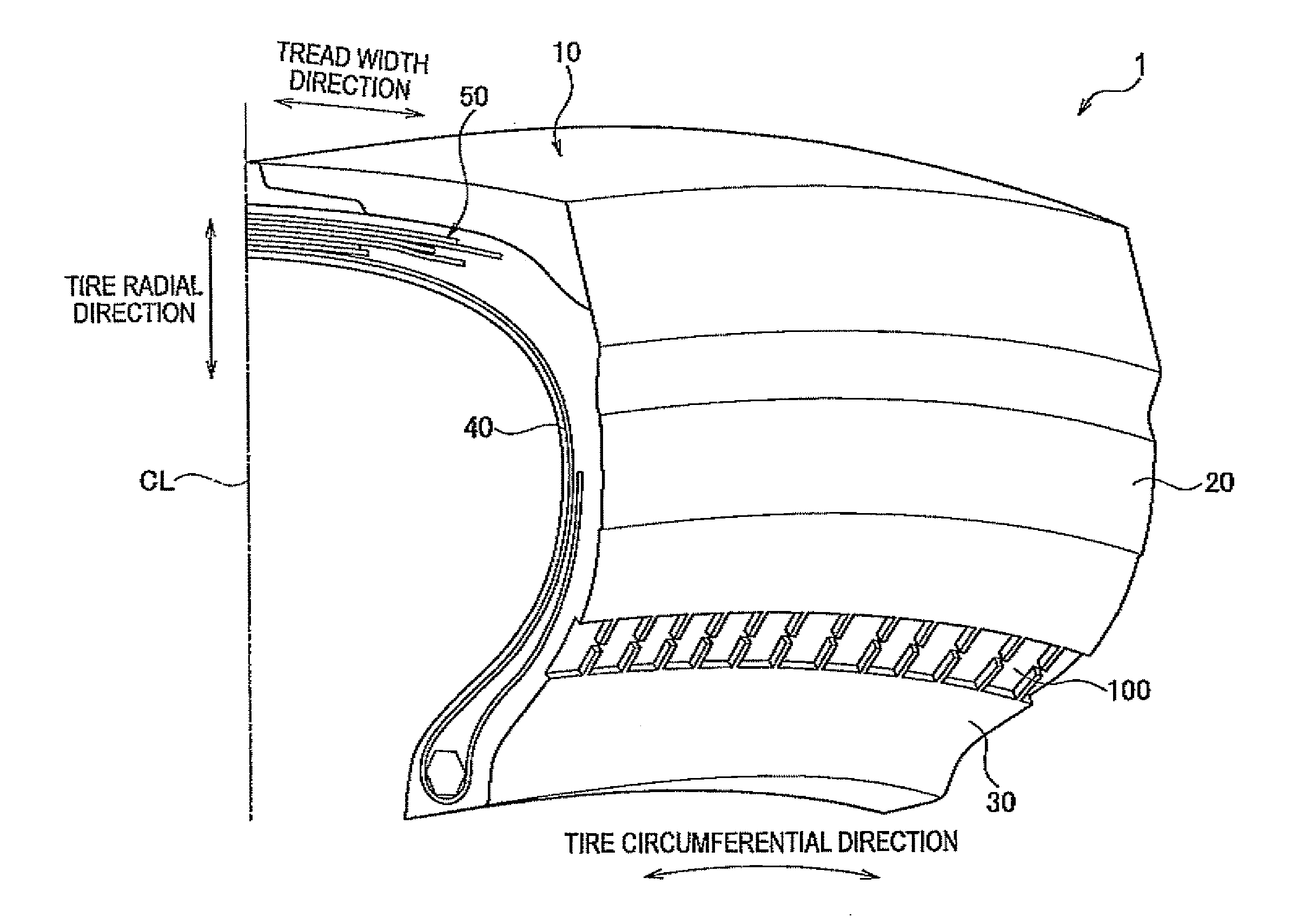
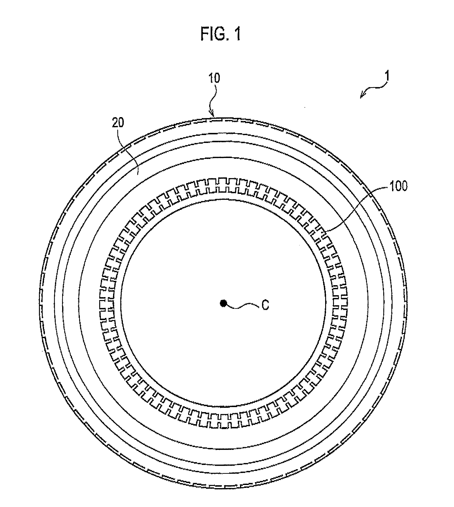
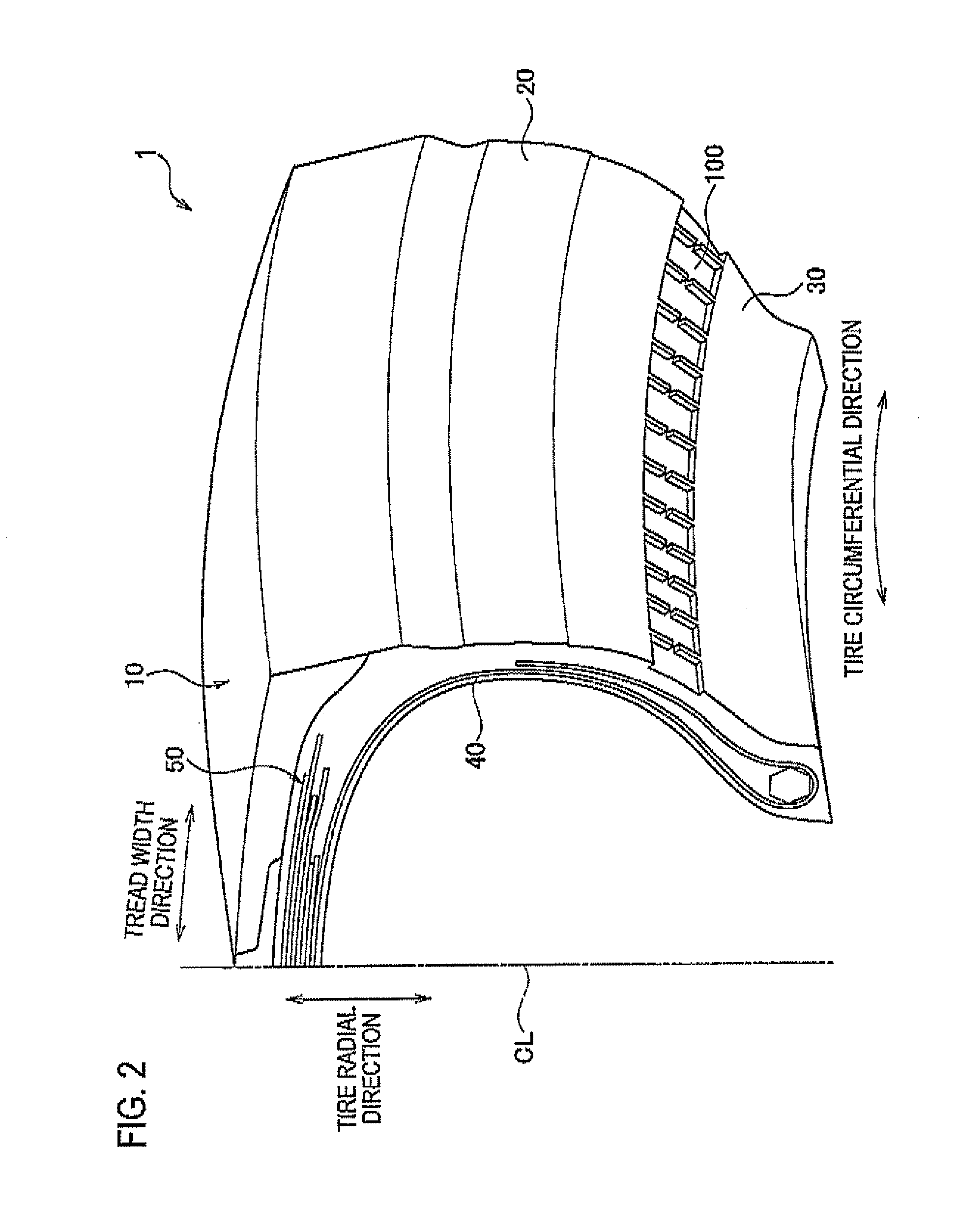
[0045]A pneumatic tire 1 according to the present embodiment is a pneumatic tire for a heavy load, which is mounted in a construction vehicle such as a dump truck. The configuration of the pneumatic tire 1 will be described with reference to the drawings. FIG. 1 is a diagram seen from a side wall surface at a tire side portion 20 side in the pneumatic tire 1 according to the first embodiment of the present invention. FIG. 2 is a partially exploded perspective view illustrating the pneumatic tire 1 according to the first embodiment of the present invention. FIG. 3 is a sectional view illustrating the pneumatic tire 1 according to the first embodiment of the present invention.

[0046]As illustrated in FIG. 1, the...

second embodiment

(2) Second Embodiment

[0076]Next, with reference to FIG. 6, a pneumatic tire 2 according to a second embodiment of the present invention will be described. In addition, a detailed description for the same configuration as that of the first embodiment will be appropriately omitted. FIG. 6(a) is a partially enlarged perspective view of a circumferential recessed portion 200 according to the second embodiment. FIG. 6(b) is a partially enlarged plan view of the circumferential recessed portion 200 according to the second embodiment.

[0077]The pneumatic tire 2 according to the second embodiment is formed at the tire side portion 20 thereof with the circumferential recessed portion 200. The circumferential recessed portion 200 is provided with a plurality of first blocks 210 that extend to protrude from a first wall surface 201 positioned at an outer side in the tire radial direction to an inner side in the tire radial direction. Furthermore, the circumferential recessed portion 200 is prov...

third embodiment

(3) Third Embodiment

[0084]Next, with reference to FIGS. 8(a) and (b), a pneumatic tire 3 according to a third embodiment will be described. In addition, a detailed description for the same configuration as that of the first embodiment will be appropriately omitted. FIG. 8(a) is a partially enlarged perspective view of a circumferential recessed portion 300 according to the third embodiment. FIG. 8(b) is a partially enlarged plan view of the circumferential recessed portion 300 according to the third embodiment.

[0085]The pneumatic tire 3 according to the third embodiment is formed at the tire side portion 20 thereof with the circumferential recessed portion 300. The pneumatic tire 3 is provided with a plurality of first blocks 310 that extend to protrude from a first wall surface 301 positioned at an outer side in the tire radial direction to an inner side in the tire radial direction and a plurality of second blocks 320 that extend to protrude from a second wall surface 302 position...


PUM


Abstract

Circumferential recesses have: first blocks protruding outward in the tire tread width direction, the first blocks having radial outer end sections and radial inner front end sections; and second blocks protruding outward in the tire tread width direction, the second blocks having radial inner end sections and radial outer front end sections. The radial inner front end sections of the first blocks and the radial outer front end sections of the second blocks are separated from each other in the tire circumferential direction or in the tire radial direction.

Description

TECHNICAL FIELD[0001]The present invention relates to a tire that suppresses an increase in the temperature of rubber of a tire side portion, particularly, a bead unit while reducing the manufacturing cost.BACKGROUND ART[0002]Conventionally, in a tire mounted in a vehicle, heat generation when the tire is rolling is problematic. An increase in the temperature of the tire due to the heat generation promotes deterioration with age such as deterioration in the physical property of the tire material, and causes the breakage and the like of a tread when the vehicle travels at a high speed. Particularly, in an off-the-road radial (ORR) tire and a truck bus radial (TBR) tire to be used with a heavy load, rubber of a bead unit is deformed by friction with a rim flange and pressure from the rim flange, so that heat is easily generated. Since the heat generation in the bead unit may promote the deterioration of the rubber of the bead unit, and reduce the endurance of the tire as well as the e...

Claims


Application Information

Patent Timeline
Patent Type & Authority Applications(United States)
IPC IPC(8): B60C13/02
CPCB60C2200/06B60C13/02
Inventor MISHIMA, SAYAKA
Owner BRIDGESTONE CORP
Why Eureka
Try Eureka