Electric rotary machine

a technology rotary machines, which is applied in the direction of dynamo-electric machines, electrical equipment, supports/enclosements/casings, etc., can solve the problems of increasing manufacturing costs, insufficient, and insufficient, and achieves uniform temperature distribution, uniform flow speed, and avoidance of the output torque of electric rotary machines

Inactive Publication Date: 2013-07-04
DENSO CORP
View PDF0 Cites 14 Cited by
  • Summary
  • Abstract
  • Description
  • Claims
  • Application Information

AI Technical Summary

Benefits of technology

[0012]In the electric rotary machine having the above structure, the cooling fluid introduced into the inside of the cooling fluid inlet passage through the inlet section flows in the cooling fluid inlet passage, and flows into the cooling fluid outlet passage through the opening section. The cooling fluid is discharged through the outlet section to the outside of the cooling fluid passage. Thus, the cooling fluid introduced into the cooling fluid passage through the inlet section flows in the cooling fluid inlet passage and the cooling fluid outlet passage in order. The cooling fluid passage is divided into the cooling fluid inlet passage and the cooling fluid outlet passage by the partition wall section ...

Problems solved by technology

However, it is not sufficient for the structure of the cooling fluid passage disclosed in the first patent document to adequately decrease the flow pressure of the cooling fluid of the spiral shaped grooves when a large amount of cooling fluid is supplied...

Method used


Image

  • Electric rotary machine
  • Electric rotary machine
  • Electric rotary machine

Examples


first exemplary embodiment

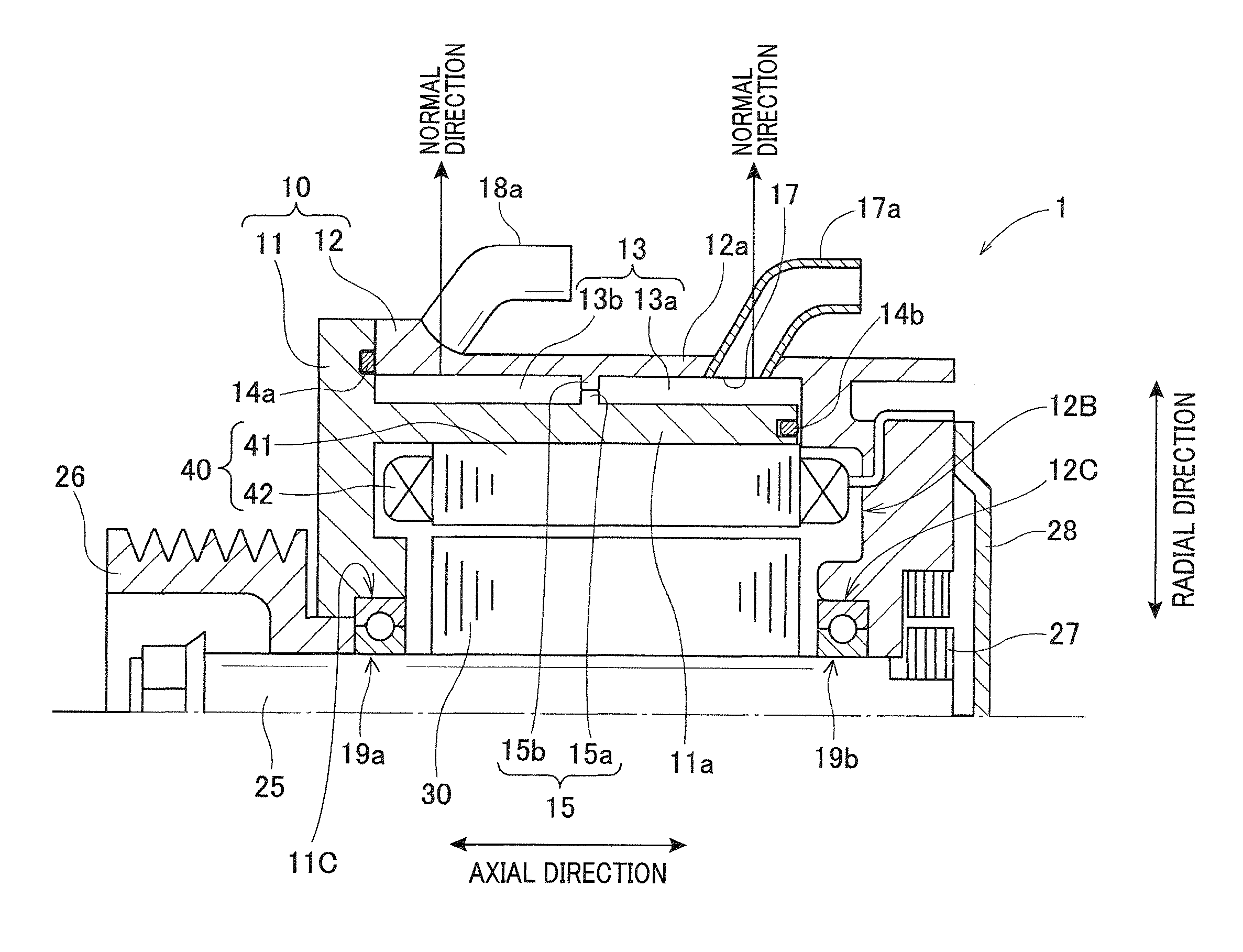
[0031]A description will now be given of an electric rotary machine 1 according to a first exemplary embodiment of the present invention with reference to FIG. 1 to FIG. 8A, FIG. 8B and FIG. 8C.

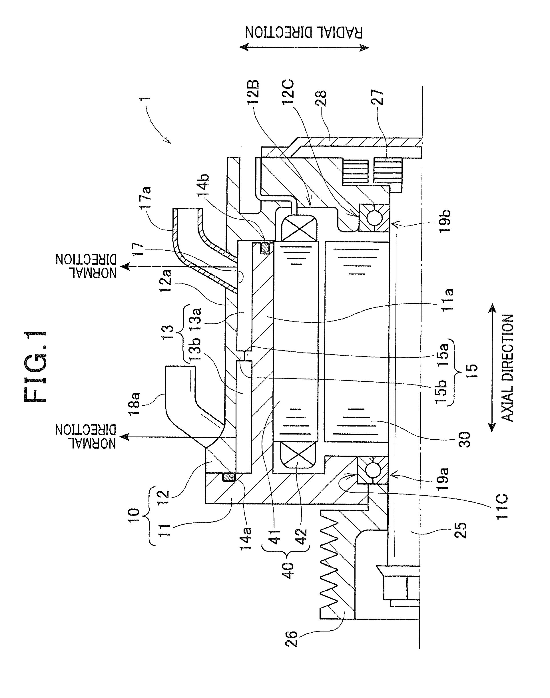
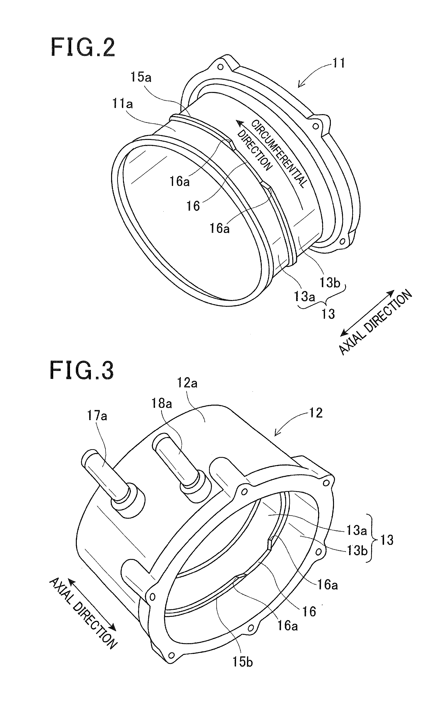
[0032]FIG. 1 is a view showing a partial cross section of an upper half of the electric rotary machine 1 in an axial direction according to the first exemplary embodiment of the present invention. FIG. 2 is a perspective view of a first motor frame 11 in the motor frame 10 of the electric rotary machine 1 according to the first exemplary embodiment shown in FIG. 1. FIG. 3 is a perspective view of a second motor frame 12 in the motor frame 10 of the electric rotary machine 1 according to the first exemplary embodiment shown in FIG. 1. FIG. 4 is a view showing a relationship between a partition wall section 15 composed of an inner partition wall section 15a and an outer partition wall section 15b, an opening section 16, an inlet section 17 connected to an inlet pipe 17a and an outlet section 18...

first modification

[0076]A description will now be given of a first modification of the partition wall section formed in the motor frame of the electric rotary machine with reference to FIG. 5.

[0077]FIG. 5 is a view showing a cross section of a motor frame 10-1 composed of a first motor frame 11-1 having a partition wall section 55 and a second motor frame 12-1 without a partition wall section in the electric rotary machine 1 according to a first modification of the first exemplary embodiment of the present invention.

[0078]As shown in FIG. 5, in the structure of the electric rotary machine 1 according to the first modification, the partition wall section 55 is formed on the first motor frame 11-1 only. That is, the second motor frame 12-1 has no partition section. Like the partition wall section 15 disclosed in the first exemplary embodiment previously described, the presence of the partition wall section 55 can provide cooling fluid having a uniform distribution of flow speed. That is, the structure ...

second modification

[0080]A description will now be given of a second modification of the partition wall section formed in the motor frame of the electric rotary machine 1 with reference to FIG. 6.

[0081]FIG. 6 is a view showing a cross section of a motor frame 10-2 composed of a first motor frame 11-2 and a second motor frame 12-2 having a partition wall section 65 in the electric rotary machine 1 according to a second modification of the first exemplary embodiment of the present invention.

[0082]As shown in FIG. 6, in the structure of the electric rotary machine 1 according to the second modification, the partition wall section 65 is formed on the second motor frame 12-2 only, not formed on the first motor frame 11-2. Like the partition wall section 15 disclosed in the first exemplary embodiment previously described, the presence of the partition wall section 65 can provide cooling fluid having a uniform distribution of flow speed. That is, the structure of the motor frame 10-2 makes it possible to uni...


PUM


Abstract

An electric rotary machine has a motor frame having a cooling fluid passage, a rotary shaft rotatably supported by the motor frame, a rotor fixed to the rotary shaft, and a stator. The stator has a core having a ring shape and a stator winding wound around the core. The stator core is arranged to face an outer periphery of the rotor in a radial direction. An inlet section and an outlet section are formed in the motor frame. Cooling fluid is introduced into the cooling fluid passage through the inlet section and discharged from the outlet section. A partition wall section is formed on the motor frame and divides the cooling fluid passage into a cooling fluid inlet passage and a cooling fluid outlet passage. Through an opening formed in the partition wall section, the cooling fluid inlet passage and the cooling fluid outlet passage communicate with each other.

Description

CROSS-REFERENCE TO RELATED APPLICATION[0001]This application is related to and claims priority from Japanese Patent Application No. 2011-289584 filed on Dec. 28, 2011, the contents of which are hereby incorporated by reference.BACKGROUND OF THE INVENTION[0002]1. Field of the Invention[0003]The present invention relates to electric rotary machines to be used as electric motors and electric generators in motor vehicles, etc.[0004]2. Description of the Related Art[0005]There is a conventional electric rotary machine which is widely known in general. Such an electric rotary machine is composed of a rotary shaft, a rotor and a stator. The rotary shaft is rotatably supported by a motor frame having a cylindrical shape. The rotor is fixed to the rotary shaft and arranged in the motor frame. The stator has a stator core and a stator winding. The stator core has a ring shape and is supported by the motor frame. The stator core is arranged at an outer periphery of the rotor to face the rotor ...

Claims


Application Information

Patent Timeline
IPC IPC(8): H02K9/193
CPCH02K5/20H02K9/193H02K9/19H02K5/203
Inventor TAKEI, TOSHIHIRO
Owner DENSO CORP
Why Eureka
Try Eureka