Stator structure of motor

Inactive Publication Date: 2013-07-04
CHANG FANG FU
View PDF6 Cites 8 Cited by
  • Summary
  • Abstract
  • Description
  • Claims
  • Application Information

AI Technical Summary

Benefits of technology

[0010]In light of the above-mentioned disadvantages of the prior art, the invention provides “a stator structure of motor” that is capable of overcoming the shortcomings of the prior art, satisfying

Problems solved by technology

However, the demerit of the motor of the prior art is that the coil having the slot leg (13) with fixed width “W” wound around to generate magnetic forc

Method used


Image

  • Stator structure of motor
  • Stator structure of motor
  • Stator structure of motor

Examples


Embodiment Construction

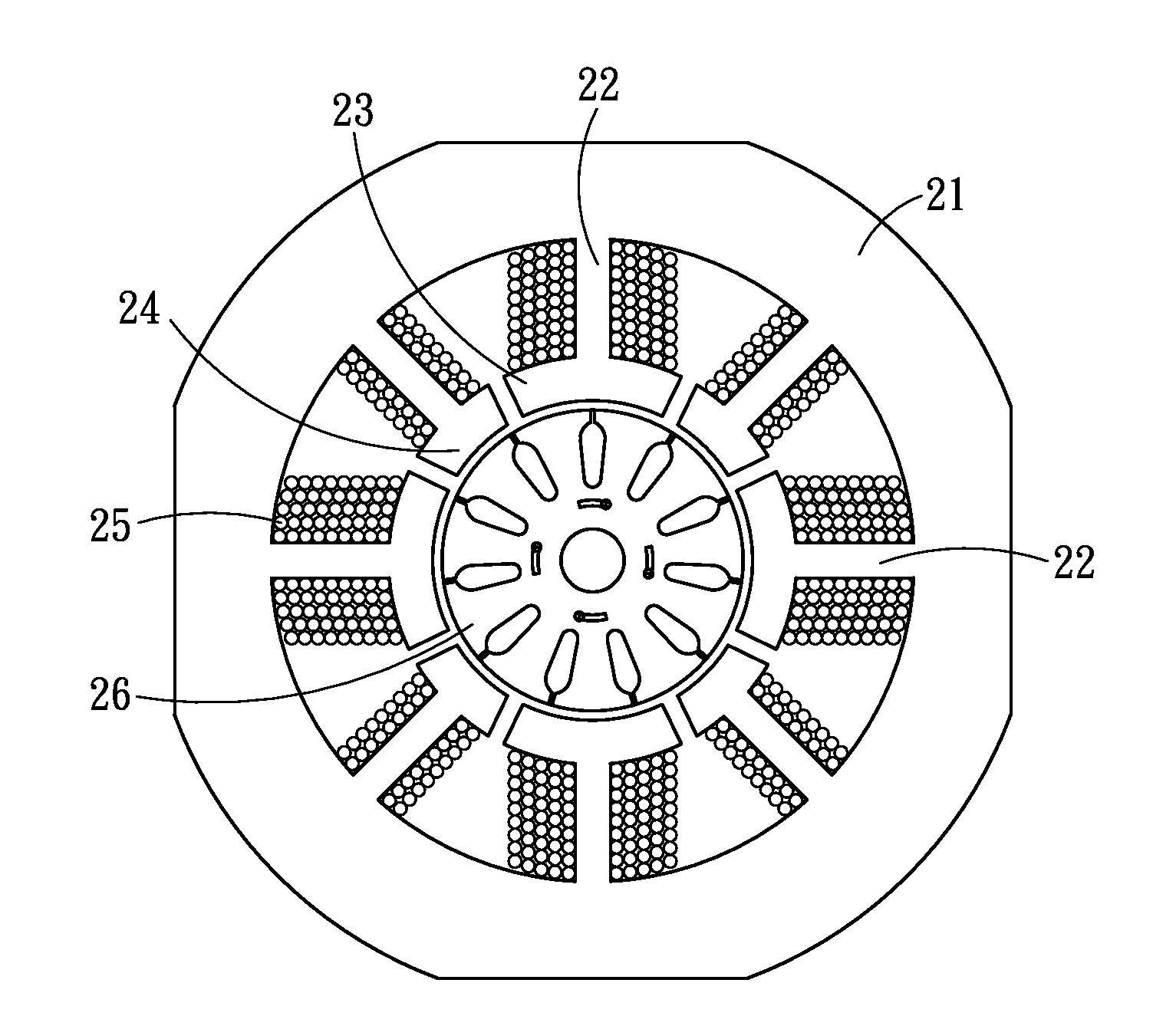
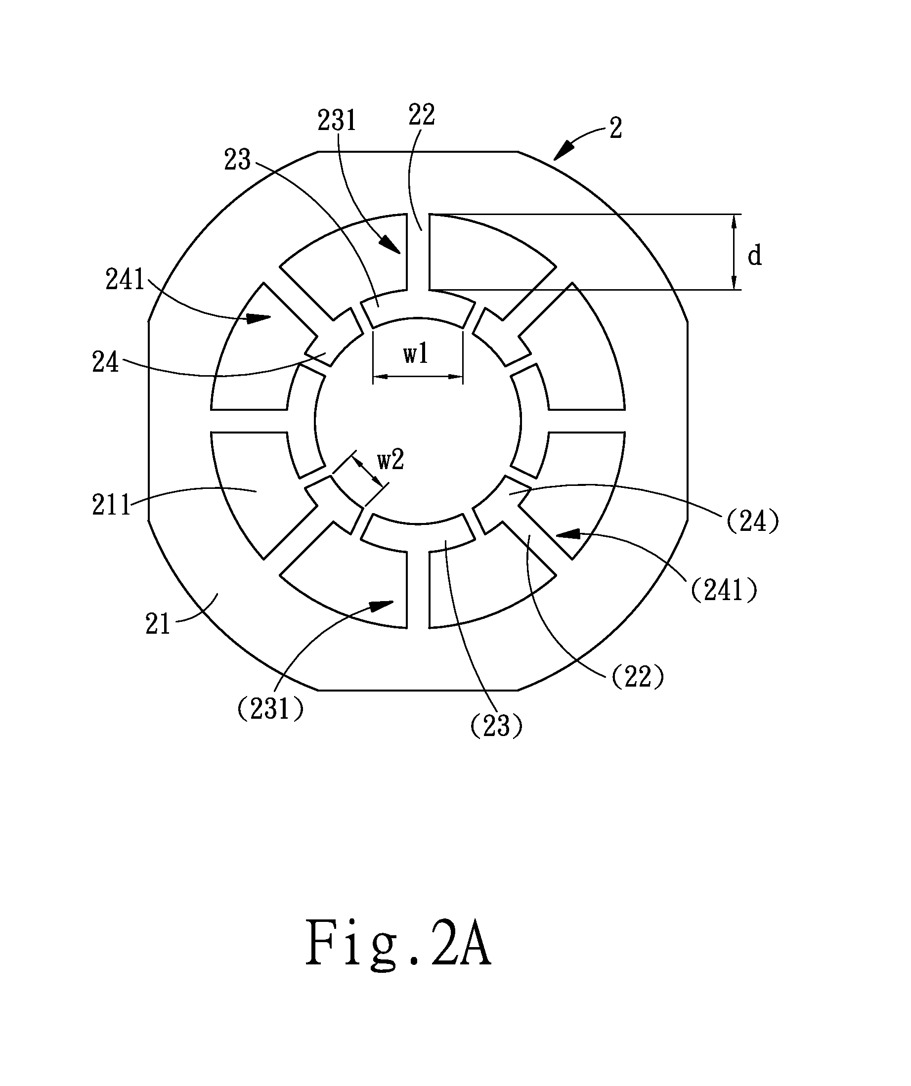
[0017]FIG. 2A is a cross-sectional view of the stator structure of the motor of a preferred embodiment of the invention while FIG. 2B is a cross-sectional view of the coil winding of stator structure of the motor of a preferred embodiment of the invention. As shown in FIG. 2A and FIG. 2B, the stator structure of motor (2) of the invention includes at least an outer ring part (21), a plurality of salient ribs (22), a plurality of first slot legs (23), a plurality of second slot legs (24), and a winding (25). The outer ring part (21) has a plurality of containing slots (211) that are disposed around a shaft center portion in circular shape for containing a rotor (26) (as shown in FIG. 2B). One end of each of the salient ribs (22) having a length “d” is formed by having one end necked-shrunk and extended from the slot wall of the containing slots (211) while the other end is extended toward the shaft center portion to form the first slot legs (23) and the second slot legs (24).

[0018]Ea...


PUM


Abstract

A stator structure of motor includes at least an outer ring part having a plurality of containing slots, a plurality of salient ribs having a length “d”, a plurality of first slot legs having a first width “W1” and forming a first slot opening on both sides of the salient ribs with the slot wall, and a plurality of second slot legs having a second width “W2” and forming a second slot opening on both sides of the salient ribs with the slot wall. By making use of the two slot legs, the windings with appropriate number of wire-winding cycle form alternately disposed structure of unsymmetrical-width type to achieve the objective of fully utilizing the area of the slot opening making the winding is capable of generating rotational magnetic field with relatively better roundness, improving the efficiency of the electrical machine, and saving the material for the stator.

Description

BACKGROUND OF THE INVENTION[0001]1. Field of the Invention[0002]The invention relates to a stator structure of motor, and more particularly, to a stator structure of motor that is capable of generating a rotating magnetic field with better roundness, improving the efficiency of the electric machine, and saving material for the stator.[0003]2. Description of the Prior Art[0004]FIG. 1 is a cross-sectional view of the stator structure of the motor of the prior art. As shown in FIG. 1, the motor's rotor-and-stator structure (1) includes an outer ring part (11), a rotor (14), a plurality of salient ribs (12), and a plurality of slot legs (13).[0005]The outer ring part (11) has a plurality of containing slots (111). The containing slots (111) and salient ribs (12) are alternately arranged in a circular pattern while the rotor (14) is positioned in the shaft center portion.[0006]Each of the salient rib (12) is extended from the slot wall of the outer ring part (11) toward the shaft center ...

Claims


Application Information

Patent Timeline
IPC IPC(8): H02K1/16
CPCH02K1/146H02K1/16H02K17/12
Inventor CHANG, FANG-FU
Owner CHANG FANG FU
Why Eureka
Try Eureka