LED lighting device

a technology of led lighting and led current, which is applied in the direction of electric variable regulation, process and machine control, instruments, etc., can solve the problems of false operation, reduced light output, and inability to suppress the deterioration of the led for a short time, so as to avoid the extinction of the light and suppress the deterioration of the led

Active Publication Date: 2013-07-04
MITSUBISHI ELECTRIC CORP
View PDF2 Cites 9 Cited by
  • Summary
  • Abstract
  • Description
  • Claims
  • Application Information

AI Technical Summary

Benefits of technology

[0017]According to the invention, since it is configured that if either one or both of the decreased output current and the increased output voltage are detected, an occurrence of disconnection is determined, and that the power source unit is first stopped temporarily, it is possible to suppress an over-current at the time of the restoration from the disconnection without an additional component, thereby suppressing the deterioration of the LED due to the over-current. Subsequently, it is configured that the temporary stop and temporary operation of the power source unit are repeated, and that the power source unit is stopped continuously if the disconnection is not restored even when the predetermined number of times of the repetition or the predetermined period of time is reached, thereby avoiding the extinction of the light due to a false operation.

Problems solved by technology

According to Patent Document 1, even though an excessive current at the time of the occurrence of a continuous abnormal situation can be suppressed, an excessive current electrified to the LED for a short time cannot be suppressed.
Also, with the configuration of Patent Document 1, there is a problem, as indicated in Patent Document 3, such that a light output is lowered due to improper detection of abnormality caused by electrical noises, and the following false operation is unavoidable: if the output of the switching regulator is stopped by one over-current detection, the lighting is turned off even in a case of a temporal intermittence or the like.
In any of these Patent Documents 2 to 4, in order to suppress the over-current produced under the abnormal situation, a component or an auxiliary circuit for current limitation is added thereto; thus, there is a problem such that the product is enlarged, so that the cost is also increased.

Method used


Image

  • LED lighting device
  • LED lighting device
  • LED lighting device

Examples


embodiment 1

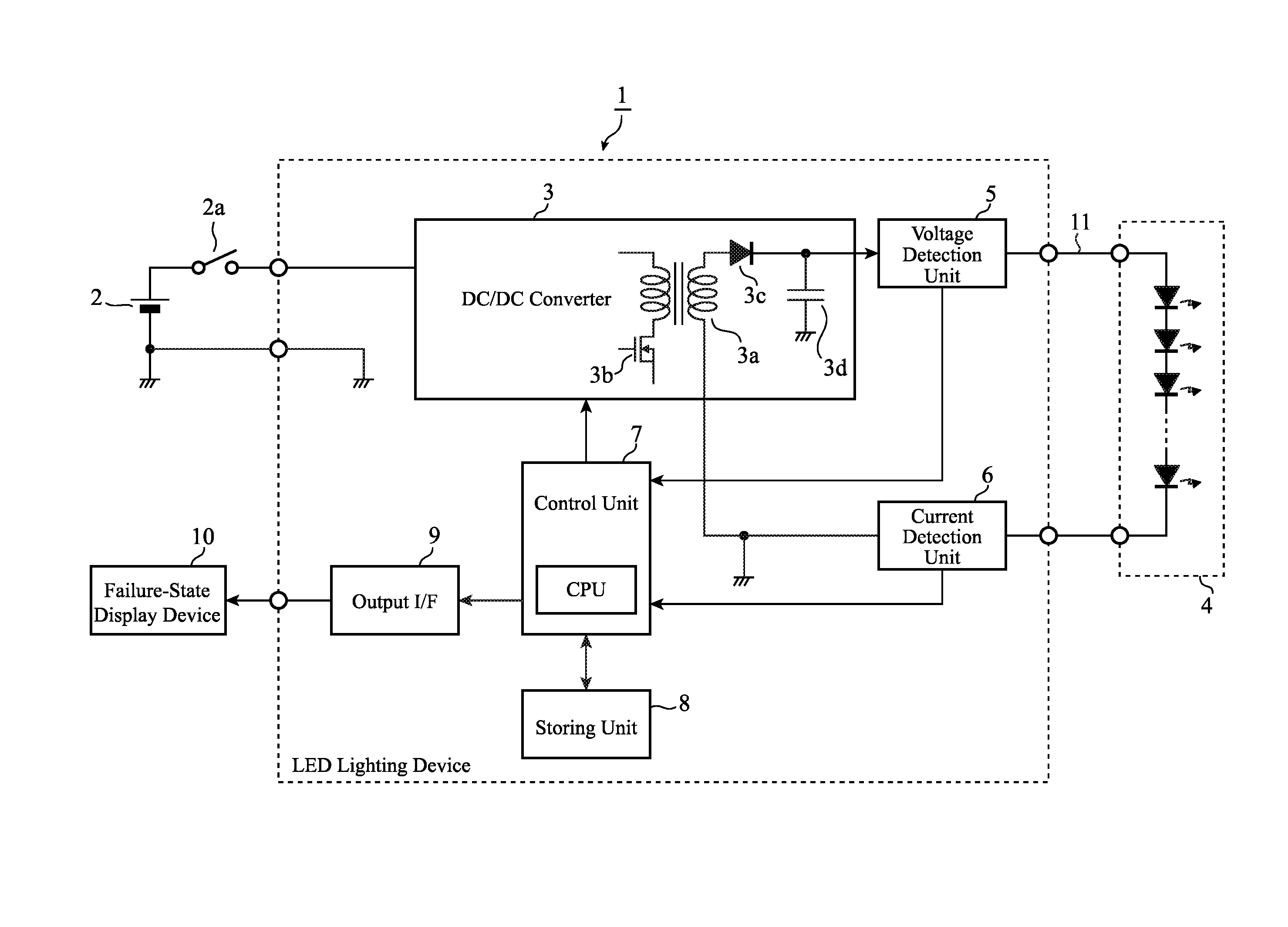
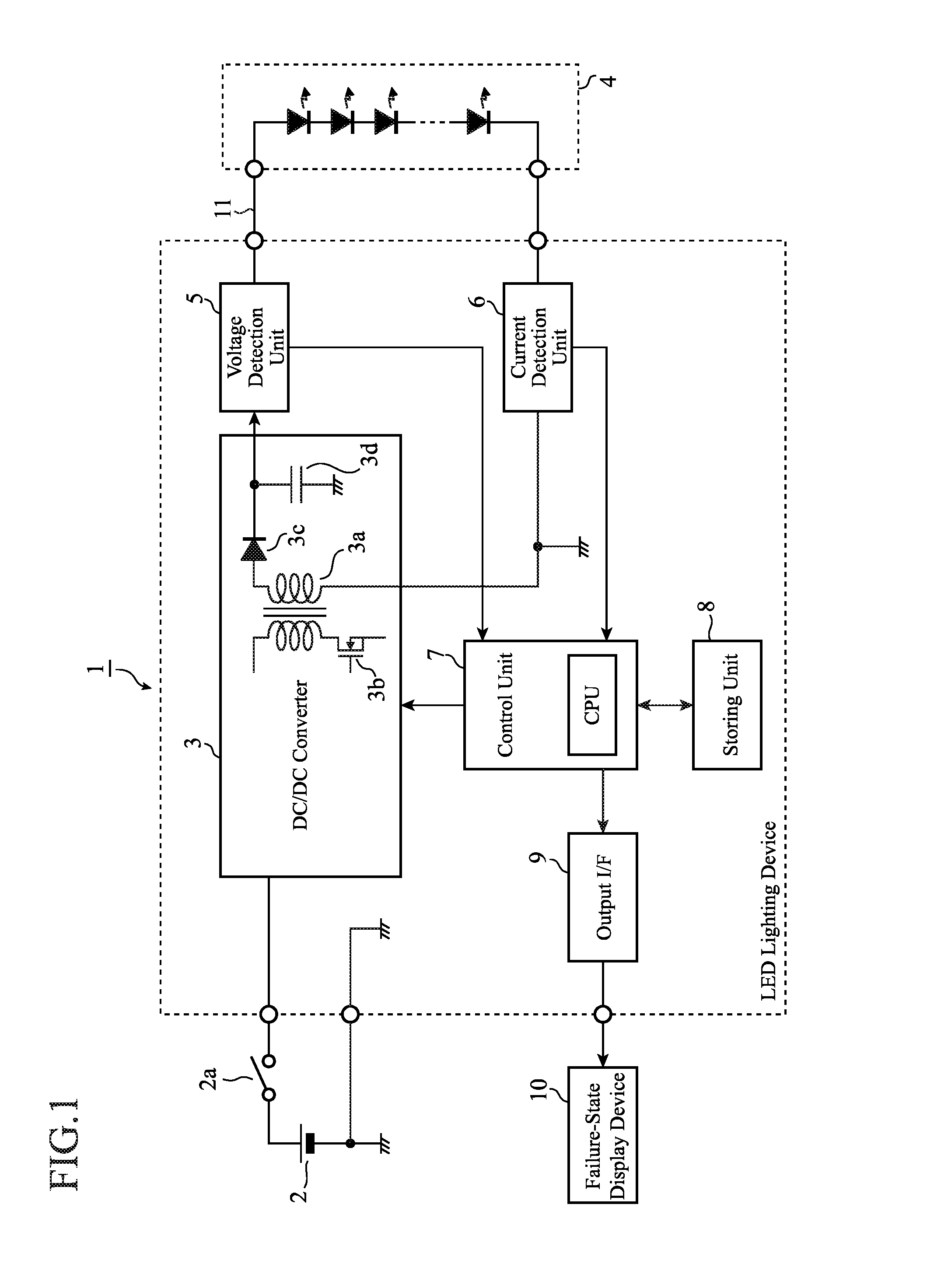
[0028]An LED lighting device 1 shown in FIG. 1 is a device for lighting an LED light source 4 by using a DC voltage from a DC power source 2, and includes a DC / DC converter 3, a voltage detection unit 5, a current detection unit 6, a control unit 7, a storing unit 8 and an output interface (hereinafter, abbreviated to “I / F”) 9. The DC power source 2 is a power source for supplying a DC voltage to the DC / DC inverter 3, and the DC voltage to the DC / DC inverter 3 is supplied or shut off by a power switch 2a. The LED light source 4 is constituted by connecting a plurality of LEDs in series and is connected to the LED lighting device 1 through a connection wiring 11. In Embodiment 1, a case where the LED light source 4 is applied to a vehicle-mounted head lamp is described by way of example. A failure-state display device 10 is what is called a telltale, and is installed inside an instrument-panel that is assembled to a dashboard.

[0029]The DC / DC converter (power source unit) 3 is constit...

embodiment 2

[0067]In the above Embodiment 1, in order to check whether the disconnection is transient or continuous, it is configured that the temporary stop and the temporary operation of the DC / DC converter 3 are repeated the predetermined number of times, whereas in Embodiment 2, it is configured that the temporary stop and temporary operation are repeated for a predetermined period of time. It is noted that since an LED lighting device of Embodiment 2 has a similar configuration in the drawing to that of the LED lighting device shown in FIG. 1, the following will be described with the aid of FIG. 1.

[0068]Next, an operation of the LED lighting device 1 according to Embodiment 2 will be described with reference to a flowchart shown in FIG. 8. Hereupon, in FIG. 8, Steps ST2 to ST7, ST10 to ST16, ST18 and ST19 are similar processes to those in FIG. 3, and hence their descriptions will be omitted; the description will be given focusing on particular Steps ST21 to ST24 in Embodiment 2.

[0069]In Em...

embodiment 3

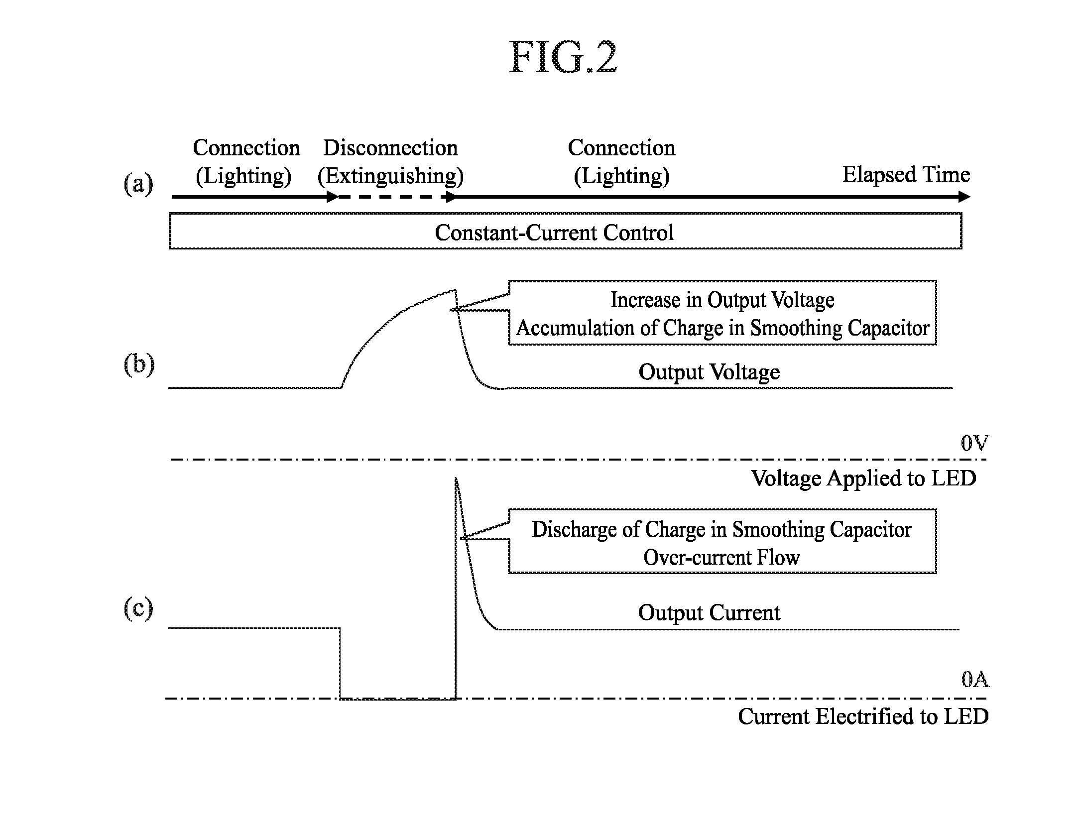
[0074]Since an LED has a constant voltage characteristic, no current is flown therein when a specific voltage is not applied thereto. Therefore, in order to carry out a conduction check of a wiring (disconnection detection process), it is necessary to apply thereto a voltage that exceeds a forward voltage of the LED. However, an application of an excessive voltage may deteriorate the LED due to an over-current at the time of the restoration of an electrification. For example, in FIG. 6, if the disconnection is restored during a first temporary operation, the over-current may be produced since a voltage higher than a set voltage is applied thereto.

[0075]Therefore, in Embodiment 3, in order to prevent the excessive voltage of the applied voltage, it is contemplated that the disconnection detection process is performed in such a manner that a voltage adding a slight margin to a voltage having been outputted in an immediately preceding normal operation is applied thereto together with a...


PUM


Abstract

When an output current is shut off by disconnection, a control unit 7 causes a DC/DC converter 3 to immediately stop temporarily for suppression of an over-current at the time of restoration, and further causes the DC/DC converter 3 to repeat an temporary stop and an temporary operation by a predetermined number of times or for a predetermined period of time, in order to check whether the shut-off of the output current is transient or continuous, and causes the DC/DC converter 3 to stop continuously if the shut off is continuous, and extinguish an LED light source 4.

Description

TECHNICAL FIELD[0001]The present invention relates to an LED lighting device for lighting an LED (Light Emitting Diode) used as a light source for vehicle-mounted head lamp and the like.BACKGROUND ART[0002]In place of a conventional halogen lamp, a long-life and maintenance-free LED has been popular as a light source used for a vehicle-mounted head lamp. Since the LED has a long life and can ensure required brightness with lower power, and further can keep almost stable brightness by simple control that supplies a constant current thereto, it is suitable for a vehicle-mounted light source.[0003]In addition, since the LED generally exhibits a constant voltage characteristic during lighting, which makes it difficult to control an amount of emission thereof based on an application voltage, it is typical to carry out the lighting through the use of a lighting device of constant-current control that outputs a constant current.[0004]Incidentally, when the LED is under lighting with the li...

Claims


Application Information

Patent Timeline
Patent Type & Authority Applications(United States)
IPC IPC(8): H05B33/08H05B44/00
CPCH05B33/0815H05B33/0878H05B33/089H05B45/3725H05B45/382H05B47/25
Inventor OOTSUKA, YASUNORIOHSAWA, TAKASHI
Owner MITSUBISHI ELECTRIC CORP
Why Eureka
Try Eureka