Methodology for Controlling A Switching Regulator Based on Hardware Performance Monitoring

Active Publication Date: 2013-07-04
NAT SEMICON CORP
View PDF6 Cites 17 Cited by
  • Summary
  • Abstract
  • Description
  • Claims
  • Application Information

AI Technical Summary

Problems solved by technology

In other example embodiments, the detected performance level corresponds to a signal path delay associated with the digital operations of the powered component.

Method used


Image

  • Methodology for Controlling A Switching Regulator Based on Hardware Performance Monitoring
  • Methodology for Controlling A Switching Regulator Based on Hardware Performance Monitoring
  • Methodology for Controlling A Switching Regulator Based on Hardware Performance Monitoring

Examples


Embodiment Construction

[0013]This Description and the Figures disclose example embodiments and applications, that illustrate various aspects and technical features of the invention disclosed and claimed in this Specification. Known circuits, functions and operations are not described in detail to avoid unnecessarily obscuring the principles and features of the claimed invention.

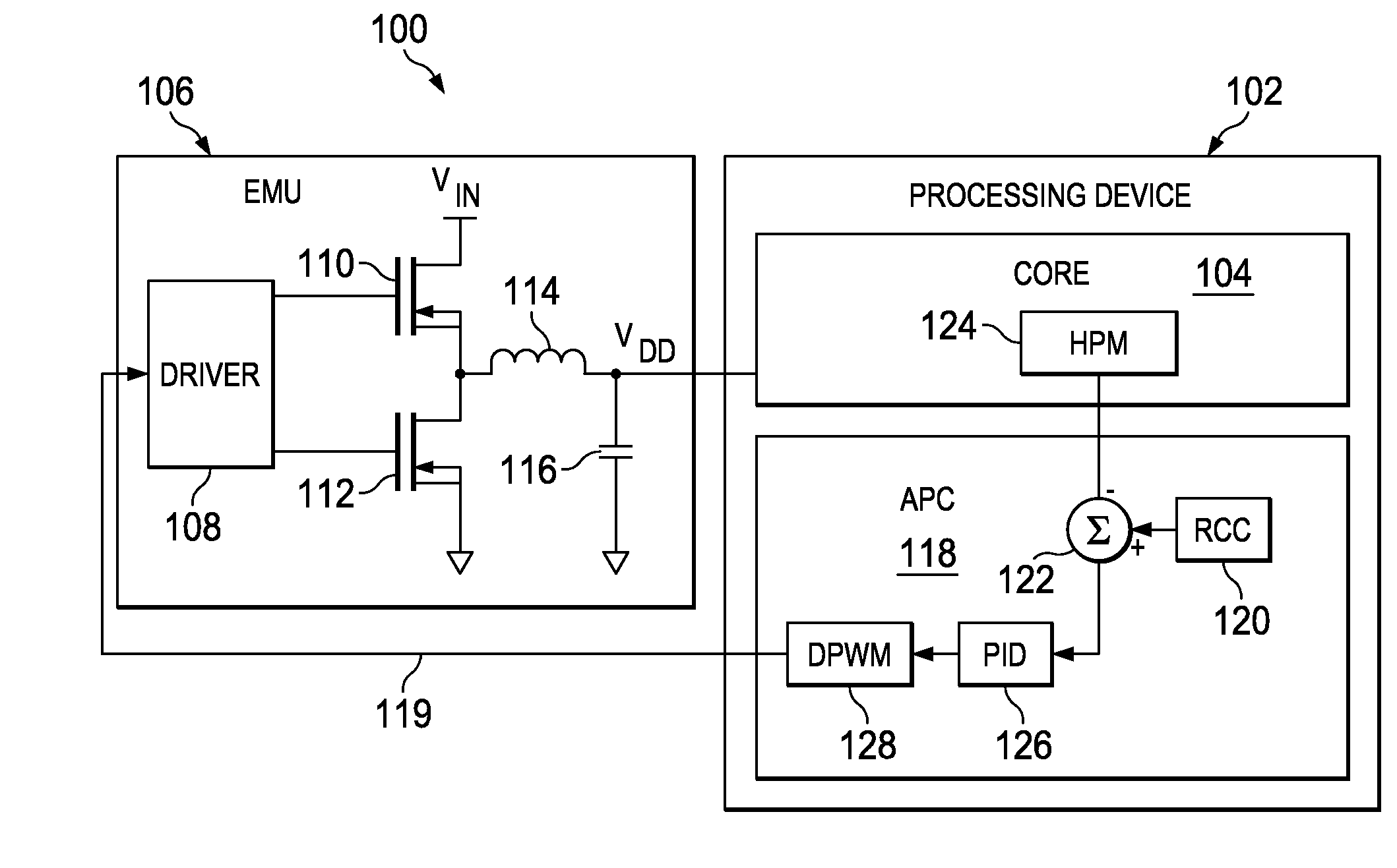
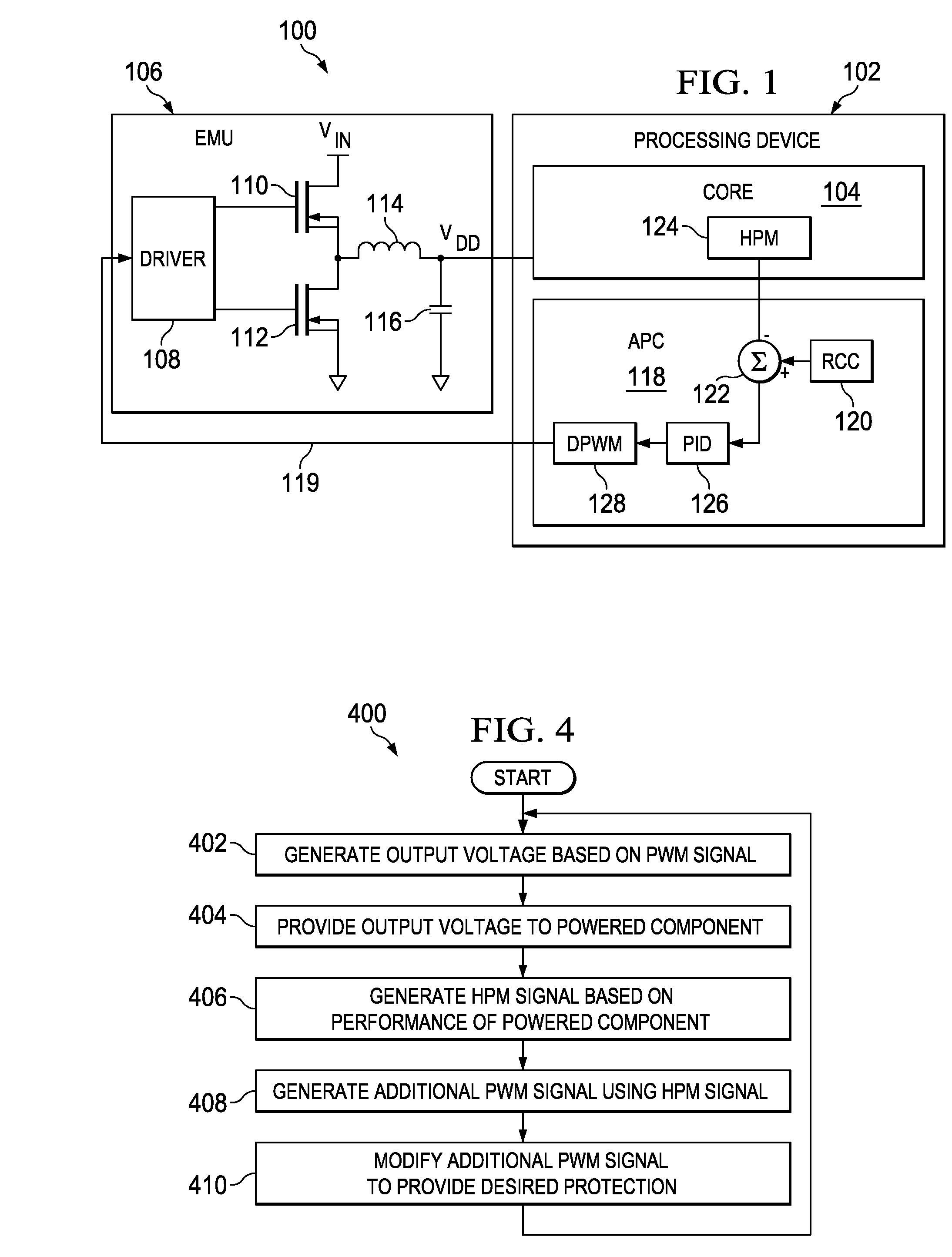
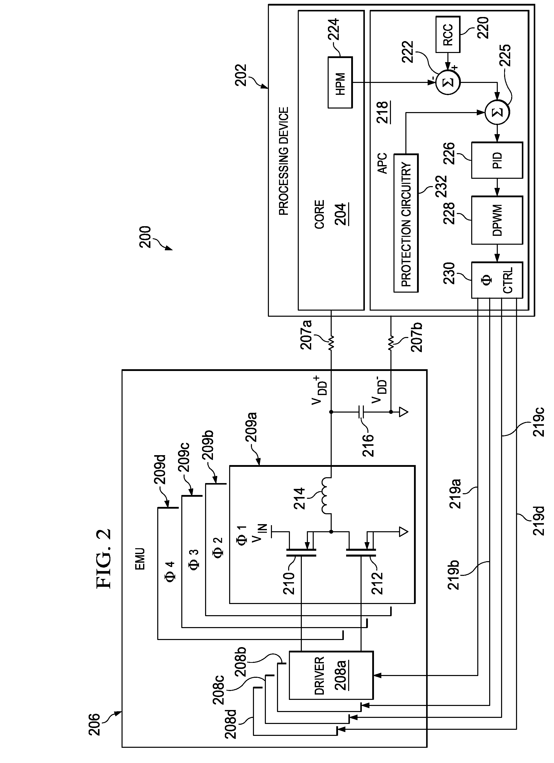
[0014]In brief overview, this Specification discloses and claims apparatus and methods for regulating power supplied to a powered component based on hardware performance associated with the powered component, such as may be used in a system that includes the powered component; and a switching regulator (EMU or energy management unit) configured to supply a regulated supply voltage to the powered component, the supply voltage being regulated in response to a switching control signal. The system includes performance monitoring circuitry configured to generate a performance monitoring signal corresponding to a detected performance lev...


PUM


Abstract

A methodology for regulating power supplied to a powered component based on hardware performance, such as may be used in a system that includes the powered component and a switching regulator (EMU or energy management unit) configured to supply a regulated supply voltage to the powered component. Performance monitoring circuitry generates a performance monitoring signal corresponding to a detected performance level of selected digital operations of the powered component relative to a reference performance level. Switching control circuitry provides a switching control signal in response to the performance monitoring signal. In an example embodiments, the switching control circuitry for the switching regulator (switching transistor) is integrated into the powered component, and the detected performance level corresponds to a detected signal path delay associated with the digital operations of the powered component.

Description

CROSS-REFERENCE TO RELATED APPLICATION[0001]This Divisional Application under 35 USC §121 claims the benefit of the filing date of U.S. application Ser. No. 12 / 592,881 (Texas Instruments docket number TI-88059, filed Dec. 4, 2009).BACKGROUND[0002]1. Technical Field[0003]This Specification is generally directed to hardware performance monitoring systems, such as adaptive voltage scaling, in which hardware performance is used in controlling the supply of power to a component or circuitry based on performance requirements.[0004]2. Related Art[0005]Adaptive voltage scaling (AVS) may be used to control the supply of power to components or circuitry based on hardware performance requirements. An example AVS system may include multiple delay cells coupled in series, where the speed of the delay cells varies based on a supply voltage. A signal can be sent through the delay cells, and the supply voltage can be adjusted until the signal reaches a first one of the delay cells and not a second ...

Claims


Application Information

Patent Timeline
Patent Type & Authority Applications(United States)
IPC IPC(8): H02J1/00
CPCH02M3/1584H02J1/00
Inventor HARTMAN, MARK
Owner NAT SEMICON CORP
Why Eureka
Try Eureka