
Catadioptric Objective for Scatterometry

Active Publication Date: 2013-07-04
ASML HLDG NV
View PDF1 Cites 3 Cited by
  • Summary
  • Abstract
  • Description
  • Claims
  • Application Information

AI Technical Summary

Benefits of technology

The patent text is looking for a special lens that can fix problems caused by how light bends in different directions. This lens will help to make pictures or videos look better.

Problems solved by technology

Reduced optical performance can lead to reduced accuracy of the OV and CD measurements, as well as reduced system productivity.
One disadvantage of previous refractive objectives is that the working distance is relatively small.
Another disadvantage of previous refractive objectives is that the operational wavelength spectral range is limited to about 450-700 nm.
Further, previous refractive objectives only have plan apochromatic aberration correction.
One disadvantage of previous catadioptric objectives is that they induce field curvature—previous catadioptric objectives typically have a large Petzval sum that is far from zero and must be corrected for.
Previous catadioptric objectives also suffer from obscuration that decreases image contrast.
Pupil aberrations in the previous catadioptric objectives are large because of large Petzval curvature and pupil size.

Method used


Image

  • Catadioptric Objective for Scatterometry
  • Catadioptric Objective for Scatterometry
  • Catadioptric Objective for Scatterometry

Examples


Embodiment Construction

[0023]This specification discloses one or more embodiments that incorporate the features of this invention. The disclosed embodiment(s) merely exemplify the present invention. The scope of the present invention is not limited to the disclosed embodiment(s). The present invention is defined by the claims appended hereto.

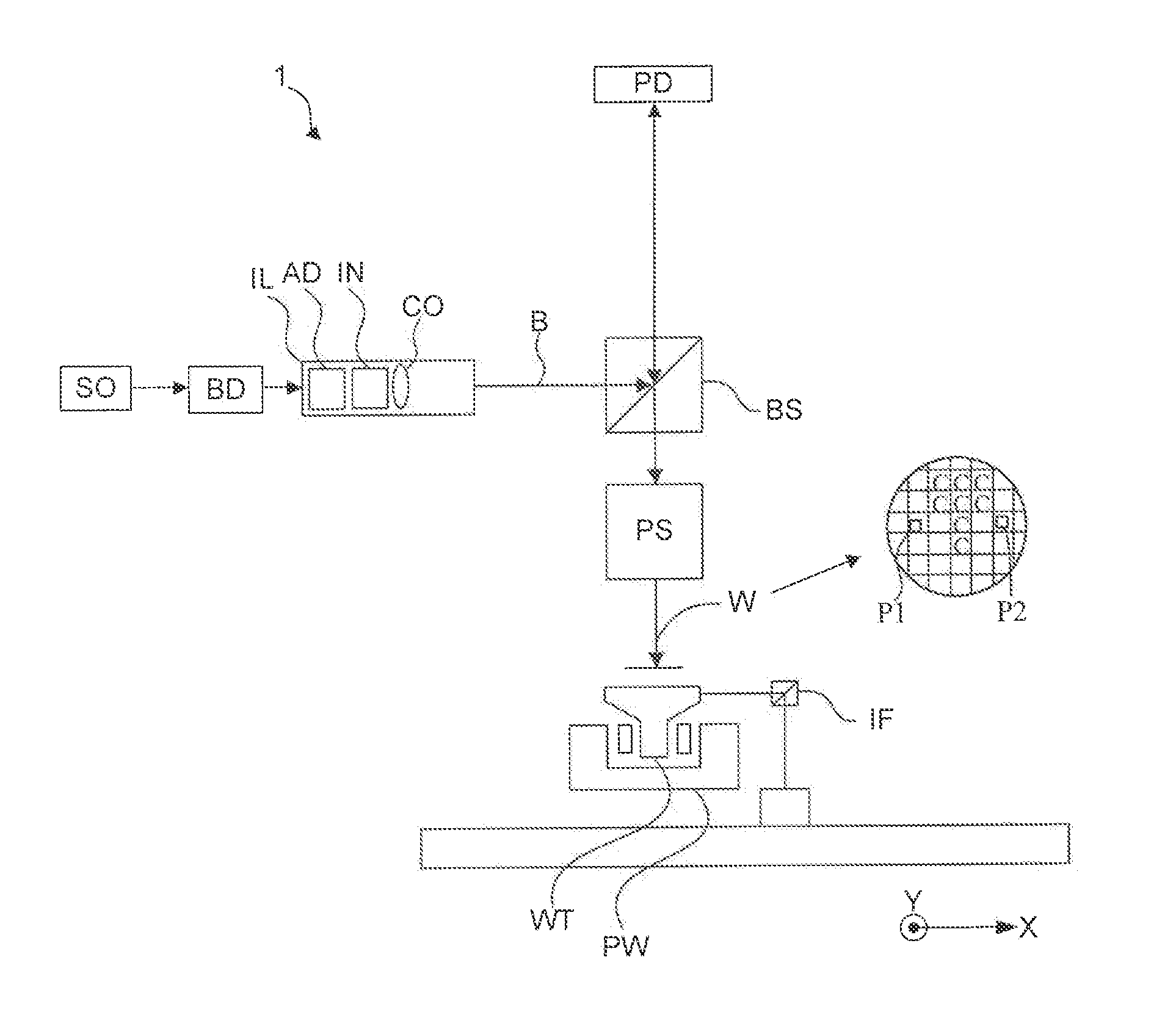
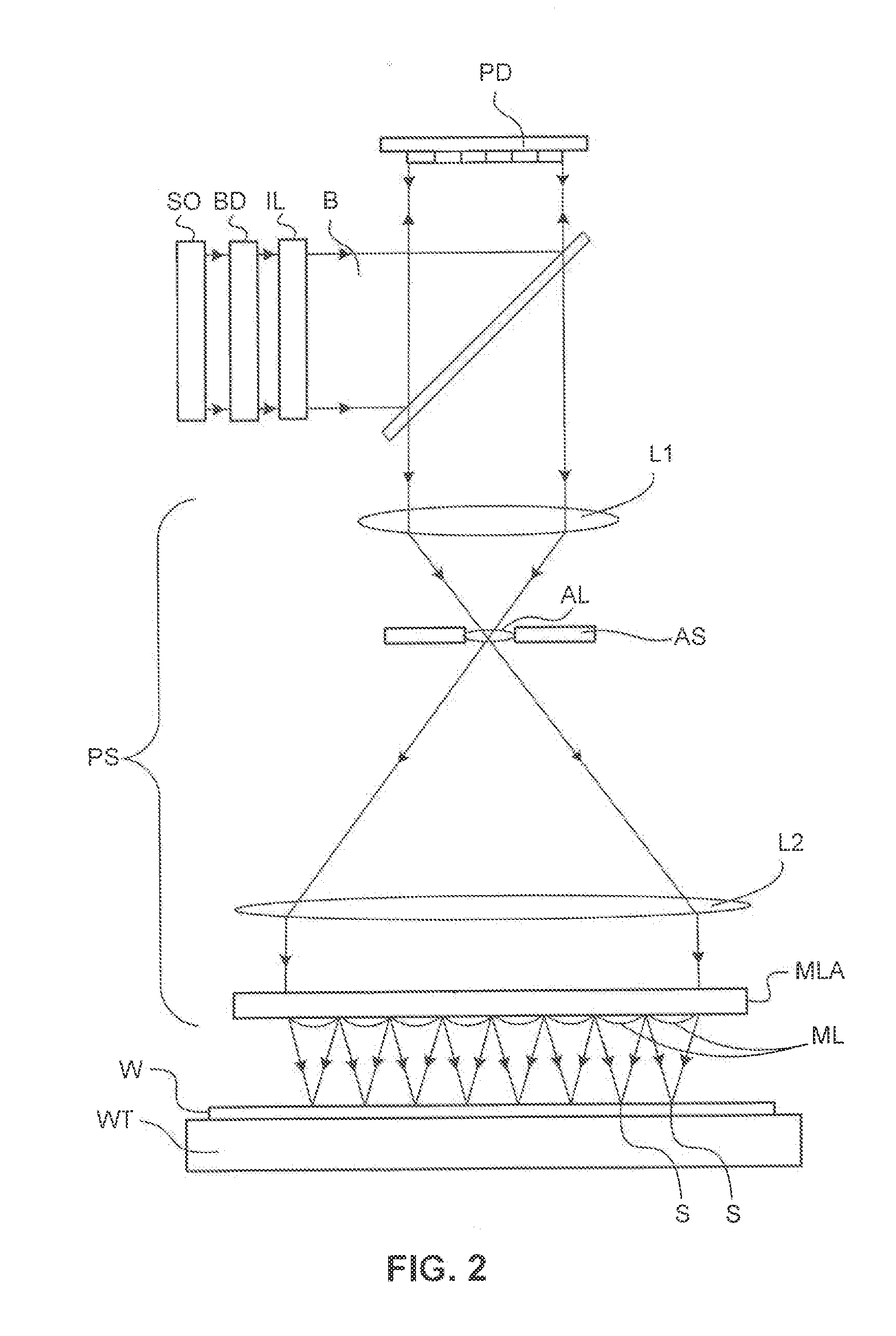
[0024]The present invention provides a system and method for correcting aberrations caused by field curvature with a catadioptric objective that may be used within an inspection apparatus such as a scatterometer. In one embodiment, a catadioptric optical system is described for deploying scatterometry in an inspection apparatus such as a scatterometer that is configured for optical metrology and may operate within a spectral band from about 200 nm to about 850 nm to make both critical dimension (CD) and overlay (OV) measurements. Scatterometry is a one of the types of metrology useful for critical dimension CD and OV related metrology. Scatterometry can measure either...


PUM


Abstract

A system and method is described for correcting aberrations caused by field curvature with a catadioptric objective. In one example, a catadioptric optical system includes a first catadioptric element and a second catadioptric element. The first catadioptric element includes a first surface positioned to reflect a beam and a second surface positioned to focus the beam reflected by the first surface. The second catadioptric element is configured to receive the beam reflected by the second surface of the first catadioptric element. The second catadioptric element includes a third surface positioned to reflect the beam, and a fourth reflective surface positioned to focus the beam reflected by the third reflective surface. A curvature of the third or fourth surfaces of the second catadioptric element is chosen to apply a positive contribution to a field curvature associated with the first catadioptric element.

Description

BACKGROUND[0001]2. Field[0002]The present invention relates to objective designs within an inspection apparatus usable, for example, in the manufacture of devices by lithographic techniques.[0003]2. Related Art[0004]A lithographic apparatus is a machine that applies a desired pattern onto a substrate, usually onto a target portion of the substrate. A lithographic apparatus can be used, for example, in the manufacture of integrated circuits (ICs). In that instance, a patterning device, which is alternatively referred to as a mask or a reticle, may be used to generate a circuit pattern to be formed on an individual layer of the IC. This pattern can be transferred onto a target portion (e.g., comprising part of, one, or several dies) on a substrate (e.g., a silicon wafer). Transfer of the pattern is typically via imaging onto a layer of radiation-sensitive material (resist) provided on the substrate. In general, a single substrate will contain a network of adjacent target portions that...

Claims


Application Information

Patent Timeline
IPC IPC(8): G02B17/08
CPCG03F7/70633G02B17/08G03F7/70625G02B17/0892G02B17/0856
Inventor SMIRNOV, STANISLAV Y.JOOBEUR, ADELSHMAREV, YEVGENIY KONSTANTINOVICHVENKATARAMAN, ARUN MAHADEVAN
Owner ASML HLDG NV
Features
  • Generate Ideas
  • Intellectual Property
  • Life Sciences
  • Materials
  • Tech Scout
  • Unparalleled Data Quality
  • Higher Quality Content
  • 60% Fewer Hallucinations
Learn More