Pipeline with Integrated Fiber Optic Cable

a fiber optic cable and fiber optic cable technology, applied in the field of pipelines, can solve the problems of obtaining accurate pipeline temperatures, affecting the accuracy of pipeline measurements, and affecting the accuracy of pipeline measurements

Inactive Publication Date: 2013-07-04
SCHLUMBERGER TECH CORP
View PDF7 Cites 41 Cited by
  • Summary
  • Abstract
  • Description
  • Claims
  • Application Information

AI Technical Summary

Problems solved by technology

For example, without such a protective coating, a steel pipeline would quickly corrode and become compromised by the salt water of a subsea environment.
However, measuring or monitoring the temperature profile of a coated pipeline can present difficulties, particularly when the coating interposes temperature sensors and the underlying metallic surface of the coated pipeline, thereby forming a relatively high thermal resistance and preventing close contact between the sensors and the metallic surface of the pipeline.
As a result, once a pipeline has been thermally insulated with a coating, obtaining accurate pipeline temperatures, as well as measuring other pipeline parameters such as strain and deformation, becomes difficult.

Method used


Image

  • Pipeline with Integrated Fiber Optic Cable
  • Pipeline with Integrated Fiber Optic Cable
  • Pipeline with Integrated Fiber Optic Cable

Examples


Embodiment Construction

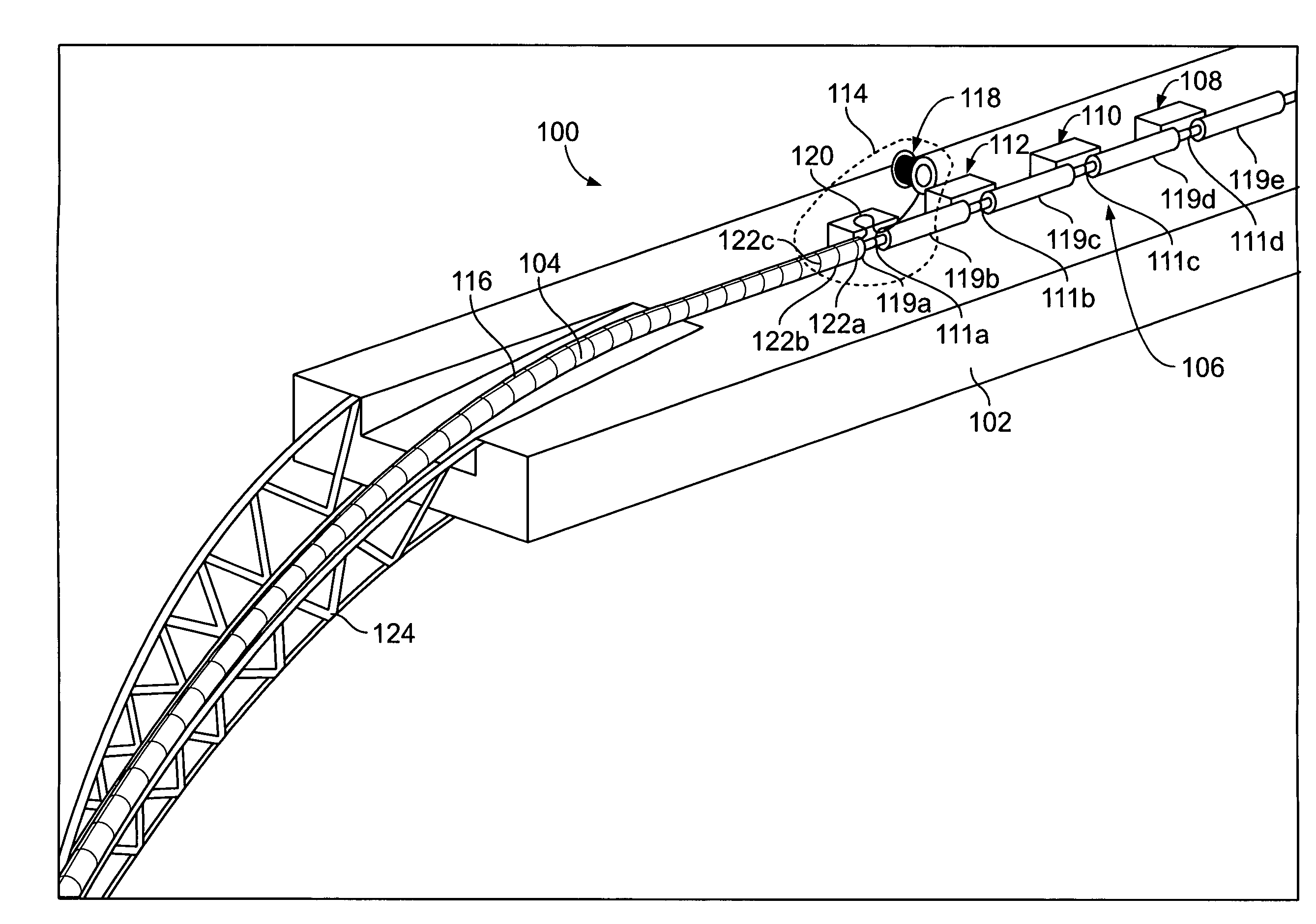
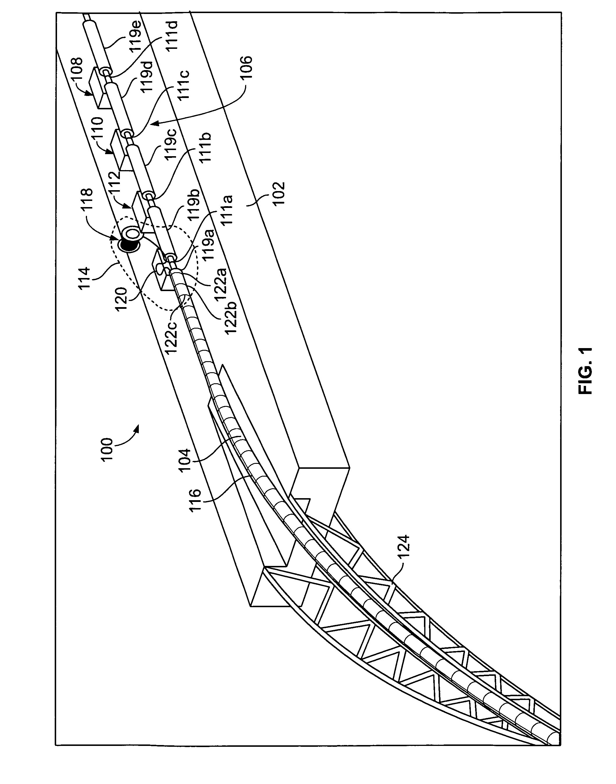
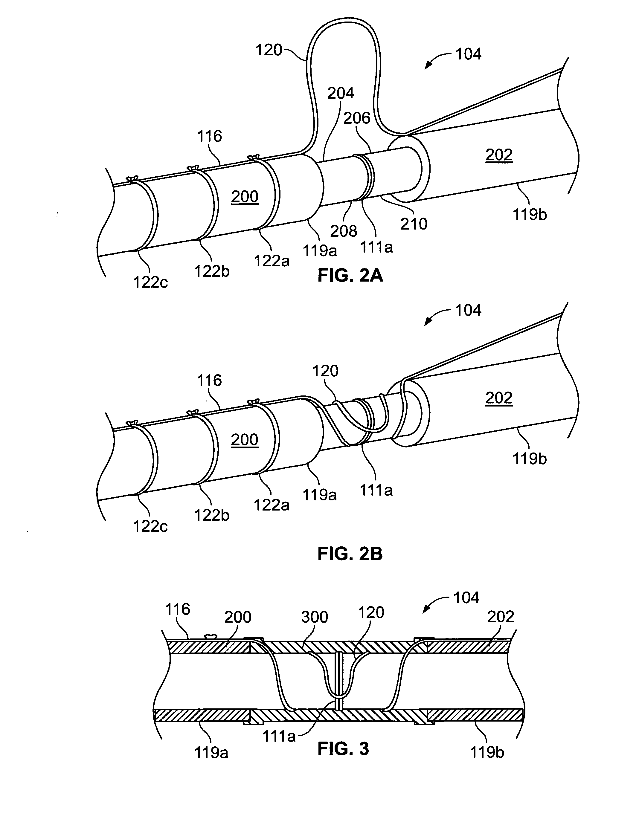
[0010]It is to be understood that the following disclosure provides different embodiments or examples for implementing different features of various embodiments. Specific examples of components and arrangements are described below to simplify the present disclosure. These are, of course, merely examples and are not intended to be limiting. In addition, the present disclosure may repeat reference numerals and / or letters in the various examples. This repetition is for the purpose of simplicity and clarity and does not in itself dictate a relationship between the various embodiments and / or configurations discussed. Moreover, the formation of a first feature over or on a second feature in the description that follows may include embodiments in which the first and second features are formed in direct contact, and may also include embodiments in which additional features may be formed interposing the first and second features, such that the first and second features may not be in direct c...


PUM

PropertyMeasurementUnit
lengthaaaaaaaaaa
lengthaaaaaaaaaa
lengthaaaaaaaaaa

Abstract

Apparatus and methods for integrating a fiber optic cable (116) with a pipeline (104) are described. An example pipeline having an integrated fiber optic cable includes a plurality of pipe sections (119a, 119b), where each of the pipe sections has a thermally insulating outer layer (200, 202) and ends not covered by the outer layer. The ends of each of the pipe sections are welded to respective ends of other pipe sections to form field joints (111a) at the welded ends. The pipeline also includes a fiber optic cable, where first portions (120) of the fiber optic cable are in contact with some of the pipe sections at some of the field joints and where second portions of the fiber optic cable between the first portions are fixed to the outer layer. A coating is applied to cover each of the first portions of the fiber optic cable to integrate the fiber optic cable with the pipeline.

Description

RELATED APPLICATION[0001]This patent claims the benefit of the filing date of U.S. Provisional Patent Application No. 61 / 378,987, filed on Sep. 1, 2010, the entire disclosure of which is incorporated by reference herein.FIELD OF THE DISCLOSURE[0002]The present disclosure relates to fluid pipelines and, more particularly, to integrating a fiber optic cable with a pipeline.BACKGROUND OF THE DISCLOSURE[0003]The production and distribution of hydrocarbon fluids such as oil and natural gas typically involves the use of long pipelines. Some production pipelines, such as those used in subsea environments, are thermally insulated to facilitate maintenance of a temperature of a fluid in the pipeline above a certain temperature. For example, the fluid may be maintained above a temperature at which wax deposits and / or hydrate plugs form. Thus, pipeline operators are often interested in monitoring the temperature profile along a pipeline, especially during a shut down operation, a start up oper...

Claims


Application Information

Patent Timeline
Patent Type & Authority Applications(United States)
IPC IPC(8): F16L1/26G01K11/32
CPCF16L13/0272F16L58/181F16L59/143F16L59/20Y10T29/49888G01M3/047F16L1/26Y10T29/49885G01K11/32G02B6/4427G02B6/46G02B6/506F16L59/14G01M3/04
Inventor ALLIOT, VINCENT
Owner SCHLUMBERGER TECH CORP
Why Eureka
Try Eureka