
Bone mineral density analysis method, bone mineral density analysis apparatus, and recording medium

a bone mineral density and analysis method technology, applied in the field of bone mineral density analysis method, bone mineral density analysis apparatus, recording medium, can solve the problems of providing voltmeters and high price of tube voltmeters

Active Publication Date: 2013-07-04
FUJIFILM CORP
View PDF4 Cites 15 Cited by
  • Summary
  • Abstract
  • Description
  • Claims
  • Application Information

AI Technical Summary

Benefits of technology

The present invention provides a method and system for analyzing bone mineral density using a DIP method. The method involves projecting radiation onto an analysis target bone portion and a reference substance with different radiation transmission characteristics, capturing a radiation image, and obtaining a bone mineral density based on the radiation transmission characteristics of the reference substance. The system includes a radiation image capturing unit, a signal processing unit, a storage unit, and a correction unit. The method and system can provide accurate bone mineral density analysis results even when using different radiation detecting bodies or capturing images under different image capturing conditions.

Problems solved by technology

In the bone mineral density analysis by DIP method described above, if the tube voltage of the radiation tube is different when capturing a radiation image by projecting radiation onto an analysis target bone portion and reference substance, such as the aluminum slope or the like, the analysis may indicate an erroneous result.
The tube voltmeter is very expensive, however, and it is undesirable to permanently provide a voltmeter in each medical institution, such as a hospital or the like, from the viewpoint of cost for bone mineral density analysis.

Method used


Image

  • Bone mineral density analysis method, bone mineral density analysis apparatus, and recording medium
  • Bone mineral density analysis method, bone mineral density analysis apparatus, and recording medium
  • Bone mineral density analysis method, bone mineral density analysis apparatus, and recording medium

Examples


Embodiment Construction

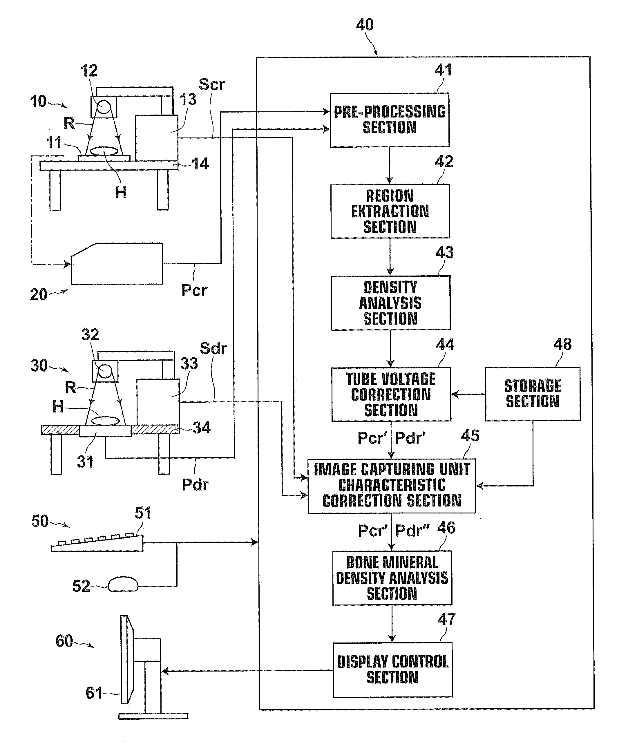
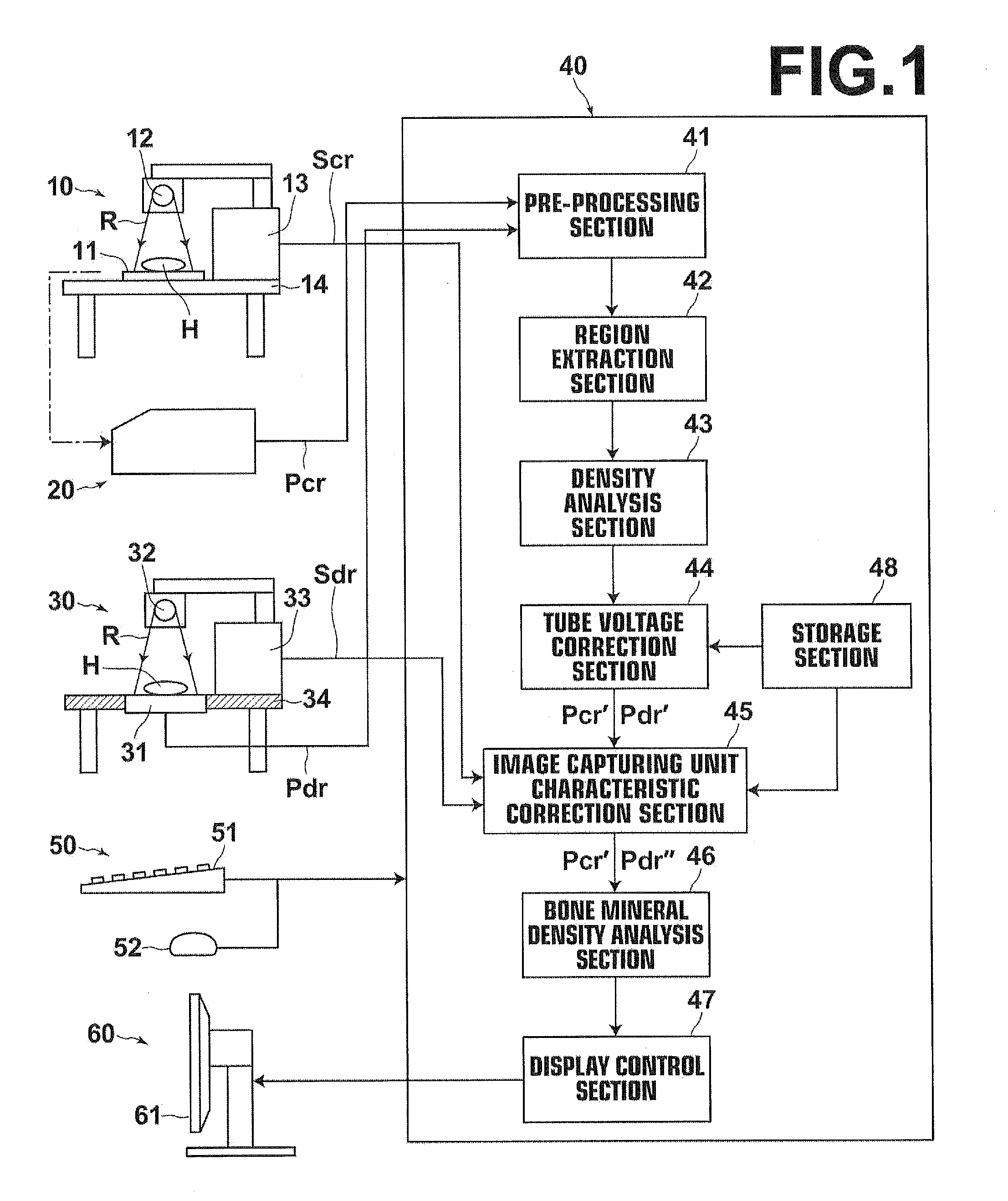
[0070]Hereinafter, embodiments of the present invention will be described in detail with reference to the accompanying drawings. FIG. 1 is a view of a system for implementing a bone mineral density analysis method according to an embodiment of the present invention, schematically illustrating the configuration thereof. The present system performs bone mineral density analysis by the DIP method described above. As illustrated in FIG. 1, the system includes: a first image capturing unit 10 for capturing and recording on a recording medium a radiation image of a subject, including a target bone portion for bone mineral density analysis; a reading unit 20 for reading the radiation image captured by the first image capturing unit 10 from the recording medium and outputting a digital image signal Pcr representing the radiation image; a second image capturing unit 30 for capturing a radiation image of the subject, including the target bone portion for bone mineral density analysis, and dir...


PUM


Abstract

From radiation images obtained by driving radiation tube with a plurality of tube voltages, including a normal tube voltage, a density gradient with respect to at least two sections of a reference substance having different radiation transmission characteristics is obtained for each of the plurality of tube voltages prior to obtaining a bone mineral density. If a radiation image captured for obtaining a bone mineral density is determined to have been captured under a tube voltage other than the normal tube voltage, an image signal representing the image and / or a bone mineral density analysis result is corrected so as to correspond to that which should have been obtained if the image had been captured under the normal tube voltage based on the relationship between the density gradient in the image and the density gradient in the radiation image captured under the normal tube voltage.

Description

BACKGROUND OF THE INVENTION[0001]1. Field of the Invention[0002]The present invention generally relates to a bone mineral density analysis method and more particularly to a bone mineral density analysis method using a radiation image of an analysis target bone portion.[0003]The invention also relates to a system for implementing the bone mineral density analysis method described above and a computer readable recording medium on which is recorded a program for causing a computer to perform the method.[0004]2. Description of the Related Art[0005]Heretofore, in order to give a diagnosis for osteoporosis and the like, analysis methods that use a radiation image of an analysis target bone portion to obtain a bone mineral density of the bone portion have been known. As one of such bone mineral density analysis methods which can be performed relatively easily, a so-called MD (Microdensitometry) method is known. Basically, in the MD method, radiation generated from a radiation tube is proje...

Claims


Application Information

Patent Timeline
Patent Type & Authority Applications(United States)
IPC IPC(8): A61B6/00
CPCA61B6/505A61B6/405A61B6/583A61B6/5217A61B6/482G16H50/30
Inventor YOSHIKAWA, KENJI
Owner FUJIFILM CORP
Learn More