Moving iron unit for loudspeakers

a technology of moving iron and loudspeaker, which is applied in the field of loudspeaker, can solve the problems of insufficient high/low frequency response, low conversion efficiency, and troublesome existing moving iron earphones, and achieve the effects of improving the mechanical shock resistance of products, improving the conversion efficiency of products, and simplifying the whole moving iron unit manufacturing process

Active Publication Date: 2013-07-04
SUZHOU YICHUAN TECH CO LTD
View PDF2 Cites 6 Cited by
  • Summary
  • Abstract
  • Description
  • Claims
  • Application Information

AI Technical Summary

Benefits of technology

[0016](1) As regards the defect of balanced armature in the prior art, this invention adopts the vibrating ring structure in place of the former balanced armature structure to significantly improve the product's mechanical shock resistance while keeping the product's magnetic circuit unobstructed;
[0017](2) This invention adopts the unique diaphragm-driven structure, in which the interaction among magnet, vibrating ring and iron core can drive two diaphragms to generate sound simultaneously. Compared to the conventional one-piece diaphragm, this design helps improve conversion efficiency of products.
[0018](3) The design of coil being directly formed on iron core, which makes the manufacture process of the whole moving iron unit simpler and more cost-effective.

Problems solved by technology

However, the existing moving iron earphone is generally troubled by shortcomings such as low conversion efficiency, insufficient high / low frequency response, low response speed, serious harmonic distortion, and susceptibility of acoustic fidelity to humidity changes.
In particular, the common U-shaped, E-shaped and flat balanced armatures (refer to FIGS. 1-3), which are usually seen in market today, all have the weakness of poor mechanical shock resistance.

Method used


Image

  • Moving iron unit for  loudspeakers
  • Moving iron unit for  loudspeakers
  • Moving iron unit for  loudspeakers

Examples


Embodiment Construction

[0025]One preferred embodiment of this invention in combination with the figures are provided as bellow:

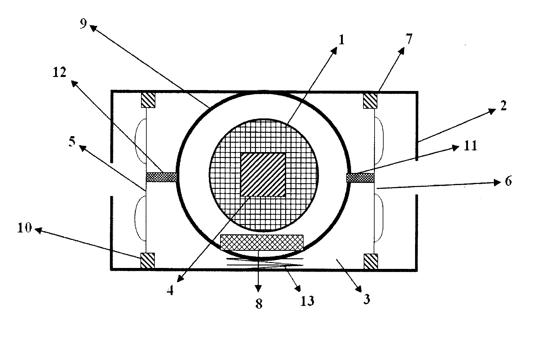
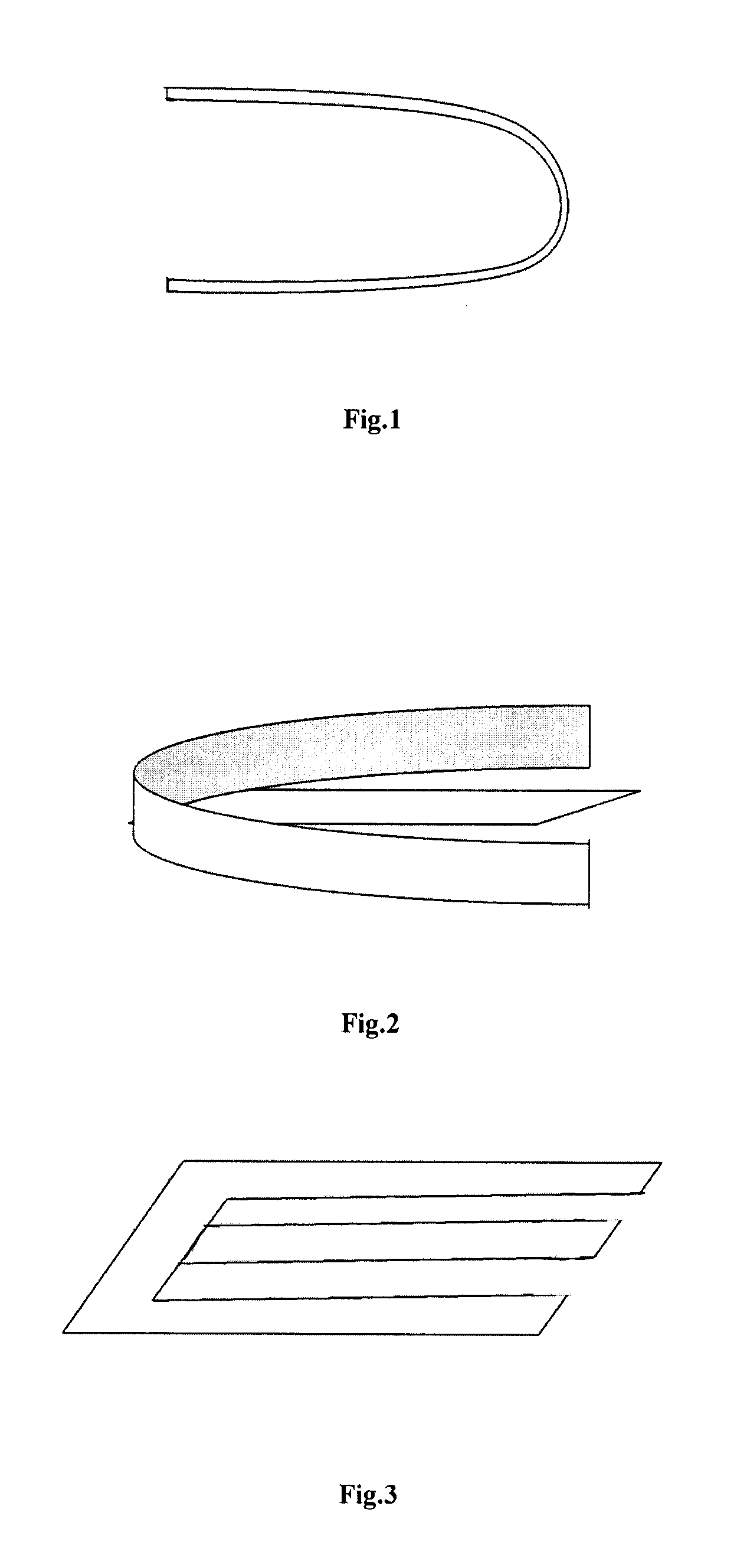
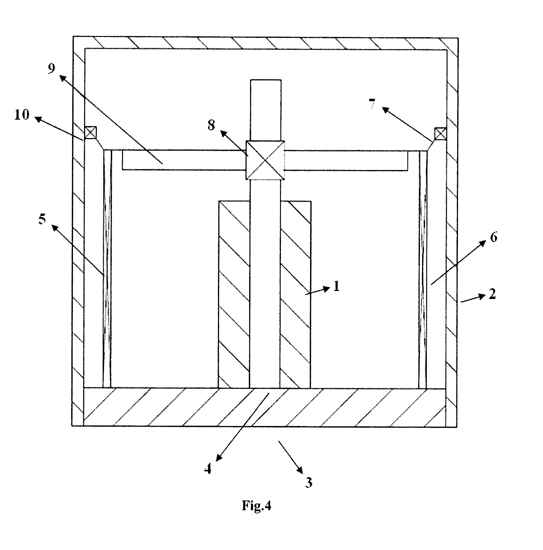
[0026]Referring to FIG. 4-5, a moving iron unit for earphones, comprises a coil 1 encapsulated in a shielded cavity, an iron core 4, a diaphragm, a magnet 8, and O-shaped vibrating ring 9; the coil 1 is set on iron core 4, the magnet 8 is secured to the vibrating ring 9, and the vibrating ring 9 is secured to the inner wall of the shielded cavity through its elastic body disposed radially and is connected to the diaphragm on a transmission basis through a transmission rod.

[0027]Preferably, the magnet is secured to one side of the vibrating ring, which is disposed coaxially with the coil and is connected to the inner wall of the shielded cavity at one side through its elastic body disposed radially, and the iron core and the coil are secured and connected to the shielded cavity at one end. Preferably, there are two diaphragms 5 and 6, which are disposed symmetrically at two sides o...


PUM


Abstract

This invention provides a moving iron unit for loudspeakers, which includes coil, iron core, diaphragm, and magnet, among which, the iron core is disposed in the coil, and the magnet is connected to the diaphragm on a transmission basis. It is characterized in that it also includes vibrating ring, to which the magnet is secured, and which is secured to the inner wall of a shielded cavity through its elastic body disposed radially, and which is connected to the diaphragm on a transmission basis through the transmission rod. Further, the unit comprises two diaphragms, which are disposed symmetrically at two sides of the vibrating ring and connected respectively to the vibrating ring on a transmission basis through a transmission rod. The coil is shaped directly by coiling on the iron core.

Description

CROSS-REFERENCE TO RELATED APPLICATIONS[0001]This application is a continuation application of International Patent Application No. PCT / CN2011 / 081816 with an international filing date of Nov. 4, 2011, designating the United States, now pending, and further claims priority benefits to Chinese Patent Application No. 201110232849.8 filed Aug. 15, 2011. The contents of all of the aforementioned applications, including any intervening amendments thereto, are incorporated herein by reference.BACKGROUND OF THE INVENTION[0002]1. Field of the Invention[0003]This invention relates to a loudspeaker, particularly to a moving iron unit applied in earphone and other miniature loudspeakers, within the field of electro acoustics and micro mechanics.[0004]2. Description of the Related Art[0005]In the moving iron earphones in the market today, the moving iron unit works by the basic principle of electronic conversion, in which the AC signals go through the magnetic induction coil, which becomes magne...

Claims


Application Information

Patent Timeline
Patent Type & Authority Applications(United States)
IPC IPC(8): H04R1/00
CPCH04R1/00H04R2209/022H04R11/02H04R7/18
Inventor ZHOU, WEI
Owner SUZHOU YICHUAN TECH CO LTD
Why Eureka
Try Eureka