Eureka AIR delivers breakthrough ideas for toughest innovation challenges, trusted by R&D personnel around the world.

Axial flow fan blade structure and axial flow fan thereof

Inactive Publication Date: 2013-07-04
ASIA VITAL COMPONENTS (CHINA) CO LTD
View PDF16 Cites 8 Cited by
  • Summary
  • Abstract
  • Description
  • Claims
  • Application Information

AI Technical Summary

Benefits of technology

The present invention provides an axial flow fan blade structure with an annular body that increases the strength of the blades and enhances the fluid efficiency of the fan. It also reduces vibration and noise made by the fan. The blade structure includes a fan impeller with multiple blades arranged annually around the hub. Each blade has a first and second flow guide face, with an annular body outward extending from the flow guide faces and connected with the blades along their length. The annular body increases the strength of the blades and reduces vibration and noise. This results in a more effective total air volume. The axial flow fan with the annular body also reduces vibration and noise and increases the air volume.

Problems solved by technology

In case the heat is not dissipated in time, the temperature of the processor will rise very quickly to deteriorate the performances of the system or even cause security problem of the system.
However, when doing this, a problem is raised.
This will cause vibration and make more noises.
However, in this case, the rigidity of the blades will be decreased to weaken the strength of the blades.
In some more serious situations, the blades may be even bent by the airflow in operation and become useless.
At the present time, the above problems remain unsolved.
1. The total fluid efficiency of the conventional axial flow fan is lowered.
2. The conventional axial flow fan is likely to vibrate and make noises.

Method used


Image

  • Axial flow fan blade structure and axial flow fan thereof
  • Axial flow fan blade structure and axial flow fan thereof
  • Axial flow fan blade structure and axial flow fan thereof

Examples


Embodiment Construction

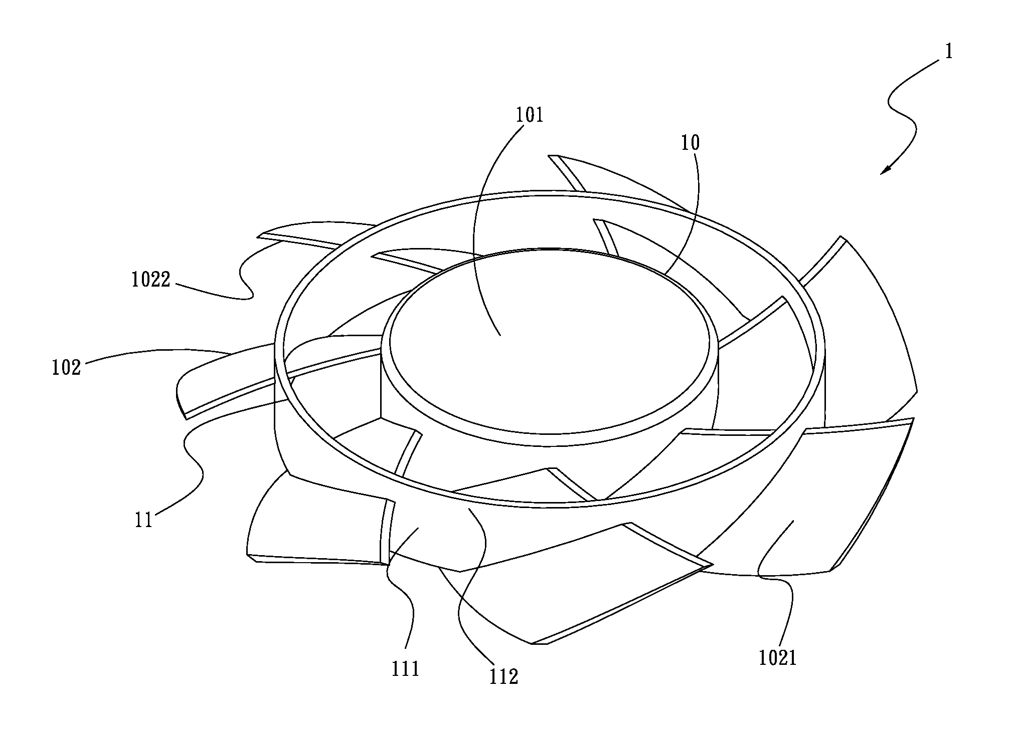
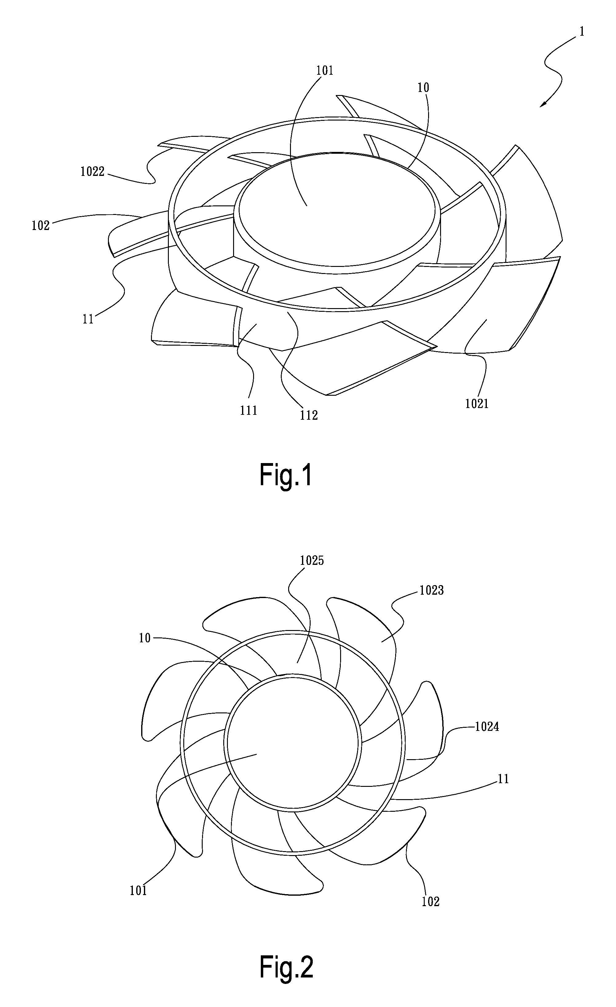
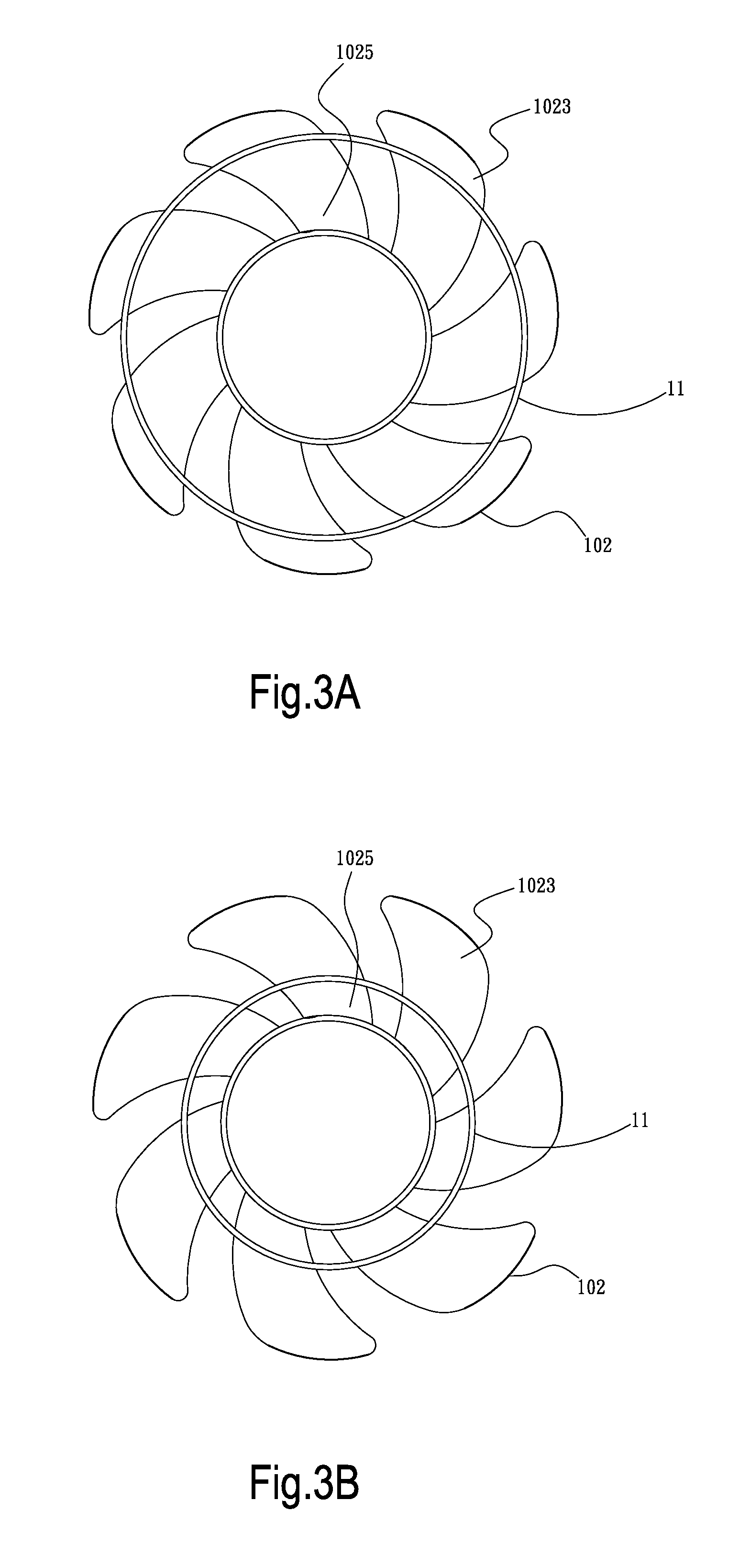
[0025]Please refer to FIG. 1, which is a perspective view of a first embodiment of the axial flow fan blade structure of the present invention. According to the first embodiment, the blade structure 1 includes a fan impeller 10 and an annular body 11. The fan impeller 10 has a hub 101 and multiple blades 102 annularly arranged along a circumference of the hub 101. Each blade 102 has a first flow guide face 1021 and a second flow guide face 1022 opposite to the first flow guide face 1021. The annular body 11 is disposed on the blades 102. The annular body 11 outward extends from the first and second flow guide faces 1021, 1022 and is annularly connected with the blades 102 along the blades 102.

[0026]The annular body 11 has multiple connection sections 111 and multiple protrusion sections 112. The connection sections 111 are connected between the adjacent blades 102. The protrusion sections 112 outward extend and protrude from the first and second flow guide faces 1021, 1022. Two side...


PUM


Abstract

An axial flow fan blade structure and an axial flow fan thereof. The axial flow fan blade structure includes a fan impeller and an annular body. The fan impeller has a hub and multiple blades. Each blade has a first flow guide face and a second flow guide face opposite to the first flow guide face. The annular body is disposed on the blades. The annular body outward extends from the first and second flow guide faces and is annularly connected with the blades along the blades. The annular body not only is able to increase the strength of the blades of the axial flow fan, but also is able to reduce vibration and noise made by the axial flow fan.

Description

BACKGROUND OF THE INVENTION[0001]1. Field of the Invention[0002]The present invention relates generally to an axial flow fan blade structure and an axial flow fan thereof. The axial flow fan blade structure includes a fan impeller and an annular body. The annular body not only is able to increase the strength of the blades of the axial flow fan, but also is able to reduce vibration and noise made by the axial flow fan so as to enhance the fluid efficiency of the axial flow fan.[0003]2. Description of the Related Art[0004]Following the continuous advance and wide application of sciences and techniques, there is a trend to real-time mass-process data. To catch up with this trend, relevant manufacturers have developed and released various high-frequency high-speed processors. In company with the development of the processors, it has become more and more critical how to solve heat dissipation problem. In operation, a processor will generate high heat. In case the heat is not dissipated ...

Claims


Application Information

Patent Timeline
IPC IPC(8): F01D5/22
CPCF04D19/002F04D29/668F04D29/388F04D29/326
Inventor CHEN, MING-JU
Owner ASIA VITAL COMPONENTS (CHINA) CO LTD
Why Eureka
Eureka Blog
Learn More