System, method, and computer software code for instructing an operator to control a powered system having an autonomous controller

a technology of autonomous controller and power system, applied in the field of powered system, can solve the problems of large variation in fuel consumption and/or emission output, difficult to achieve, and no further determination of actual emission outpu

Active Publication Date: 2013-07-04
GE GLOBAL SOURCING LLC
View PDF3 Cites 70 Cited by
  • Summary
  • Abstract
  • Description
  • Claims
  • Application Information

AI Technical Summary

Benefits of technology

[0027]In an embodiment, a method (e.g., for simulating control of a vehicle) includes presenting simulated travel of the vehicle along a route to an operator disposed onboard the vehicle while the vehicle is stationary. The simulated travel represents movements of the vehicle along the route. The method also includes monitoring manual actuation of one or more devices onboard the vehicle in order to track manual changes to simulated operational settings of the vehicle by the operator during the simulated travel of the vehicle and communicating one or more differences between the simulated operational settings that are manually provided by the operator and designated operational settings of a trip plan so that the operator can practice manual control of the vehicle along the route according to the trip plan. The trip plan includes designated operational settings of the vehicle expressed as a function of at least one of distance or time along the route for a trip.
[0028]In an embodiment, a system (e.g., a trip optimizer system) includes a vehicle controller configured to be disposed onboard a vehicle and to at least one of obtain or create a trip plan having designated operational settings of the vehicle as a function of at least one of time or distance along a route for a trip of the vehicle. The vehicle controller also is configured to at least one of (a) autonomously control actual operational settings of the vehicle as the vehicle actually travels along the route during the trip such that the vehicle travels according to the designated operational settings of the trip plan and to communicate at least one of the actual operational settings of the vehicle or changes to the actual operational settings of the vehicle to an operator as the vehicle to instruct the operator how to manually control the vehicle according to the trip plan, or (b) present simulated travel of the vehicle along the route while the vehicle is stationary, monitor manual actuation of one or more devices onboard the vehicle in order to track manual changes to simulated operational settings of the vehicle by the operator during the simulated travel of the vehicle, and communicate one or more differences between the simulated operational settings that are manually provided by the operator and designated operational settings of the trip plan so that the operator can practice manual control of the vehicle along the route according to the trip plan.

Problems solved by technology

However, typically, there is no further determination made regarding the actual emission output while the train is in idle.
When operating a train, train operators typically call for the same notch settings when operating the train, which in turn may lead to a large variation in fuel consumption and / or emission output, such as, but not limited to, NOx, CO2, etc., depending on a number of locomotives powering the train.
This is difficult to do since, as an example, the size and loading of trains vary, locomotives and their fuel / emissions characteristics are different, and weather and traffic conditions vary.
As more powered vehicles start being controlled by an autonomous, and / or an automatic, controller, skills of experienced operators may degrade while developing skills for new operators may be greatly impeded.
Though limited skills are acceptable while the autonomous, and / or automatic, controller is controlling the powered vehicles, times will arise where operators may have to take control of the powered vehicles.

Method used


Image

  • System, method, and computer software code for instructing an operator to control a powered system having an autonomous controller
  • System, method, and computer software code for instructing an operator to control a powered system having an autonomous controller
  • System, method, and computer software code for instructing an operator to control a powered system having an autonomous controller

Examples


Embodiment Construction

[0089]Reference will now be made in detail to the embodiments consistent with the invention, examples of which are illustrated in the accompanying drawings. Wherever possible, the same reference numerals used throughout the drawings refer to the same or like parts.

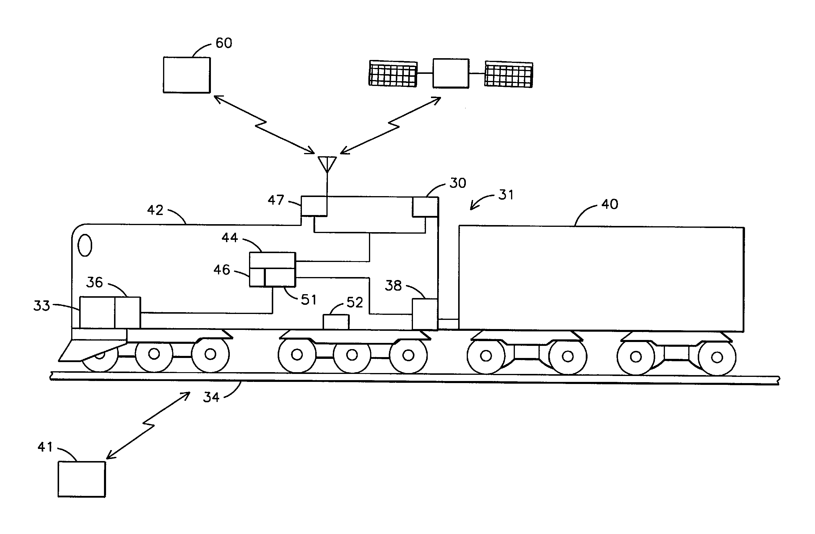
[0090]Though embodiments of the inventive subject matter are described with respect to vehicles, such as rail vehicles or railway transportation systems, specifically trains and locomotives, embodiments of the inventive subject matter are also applicable for other uses, such as but not limited to off-highway vehicles, marine vessels, stationary units, agricultural vehicles, and transport buses, each which may use at least one diesel engine, or diesel internal combustion engine. Toward this end, when discussing a specified mission, this includes a task or requirement to be performed by the powered system. Although various embodiments herein are described in connection with trains, locomotives, locomotive consists, other rai...


PUM


Abstract

A method for training an operator to control a powered system is disclosed including operating the powered system with an autonomous controller, and informing an operator of a change in operation of the powered system as the change in operation occurs. A system and a computer software code are also disclosed for training the operator to control the powered system.

Description

CROSS-REFERENCE TO RELATED APPLICATIONS[0001]This application claims priority to and is a continuation-in-part of U.S. patent application Ser. No. 12 / 128,249, filed 28 May 2008 (the '249 Application”), which is based on and claims priority to U.S. Provisional Application No. 61 / 048,344, filed 28 Apr. 2008 (the “'344 Application”).[0002]The '249 Application also claims priority to and is a continuation-in-part of U.S. application Ser. No. 12 / 061,444, filed 2-Apr.-2008 (the '444 Application”), which claims priority to U.S. Provisional Application No. 60 / 939,848, filed 23 May 2007 (the “'848 Application”), and U.S. Provisional Application No. 60 / 942,559, filed 7 Jun. 2007 (the “'559 Application”).[0003]The '249 Application also claims priority to and is a continuation-in-part of U.S. application Ser. No. 12 / 061,462, filed 2-Apr.-2008 (the '462 Application”), which claims priority to and is a continuation-in-part of U.S. application Ser. No. 11 / 765,443, filed 19 Jun. 2007 (the “'443 App...

Claims


Application Information

Patent Timeline
Patent Type & Authority Applications(United States)
IPC IPC(8): G09B19/16
CPCB61L3/006Y02T30/10B61C17/12B61L27/0055B61L2205/04G09B9/06G09B19/16G09B19/167B61L27/0027G09B9/04Y02T30/00B61L27/16B61L27/60
Inventor KUMAR, AJITH KUTTANNAIR
Owner GE GLOBAL SOURCING LLC
Why Eureka
Try Eureka