Radio measurement collection method and radio terminal
- Summary
- Abstract
- Description
- Claims
- Application Information
AI Technical Summary
Benefits of technology
Problems solved by technology
Method used
Image
Examples
first embodiment
(1) First Embodiment
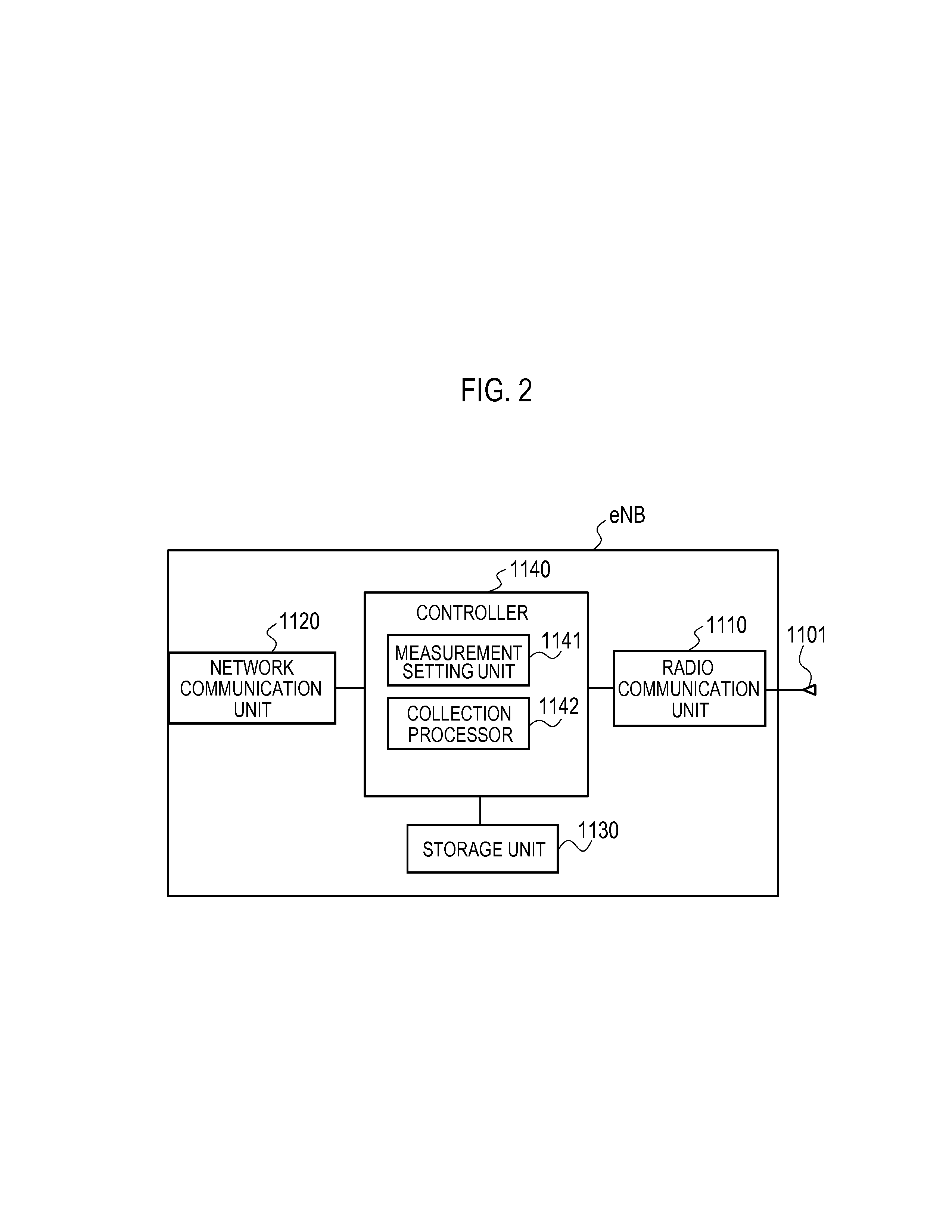
[0051]Hereinafter, the description is given in the following order of (1.1) Outline of Mobile Communication System, (1.2) Configuration of Radio Base Station, (1.3) Configuration of Radio Terminal, (1.4) Radio Measurement Collection Method, and (1.5) Effects of First Embodiment.
(1.1) Outline of Mobile Communication System
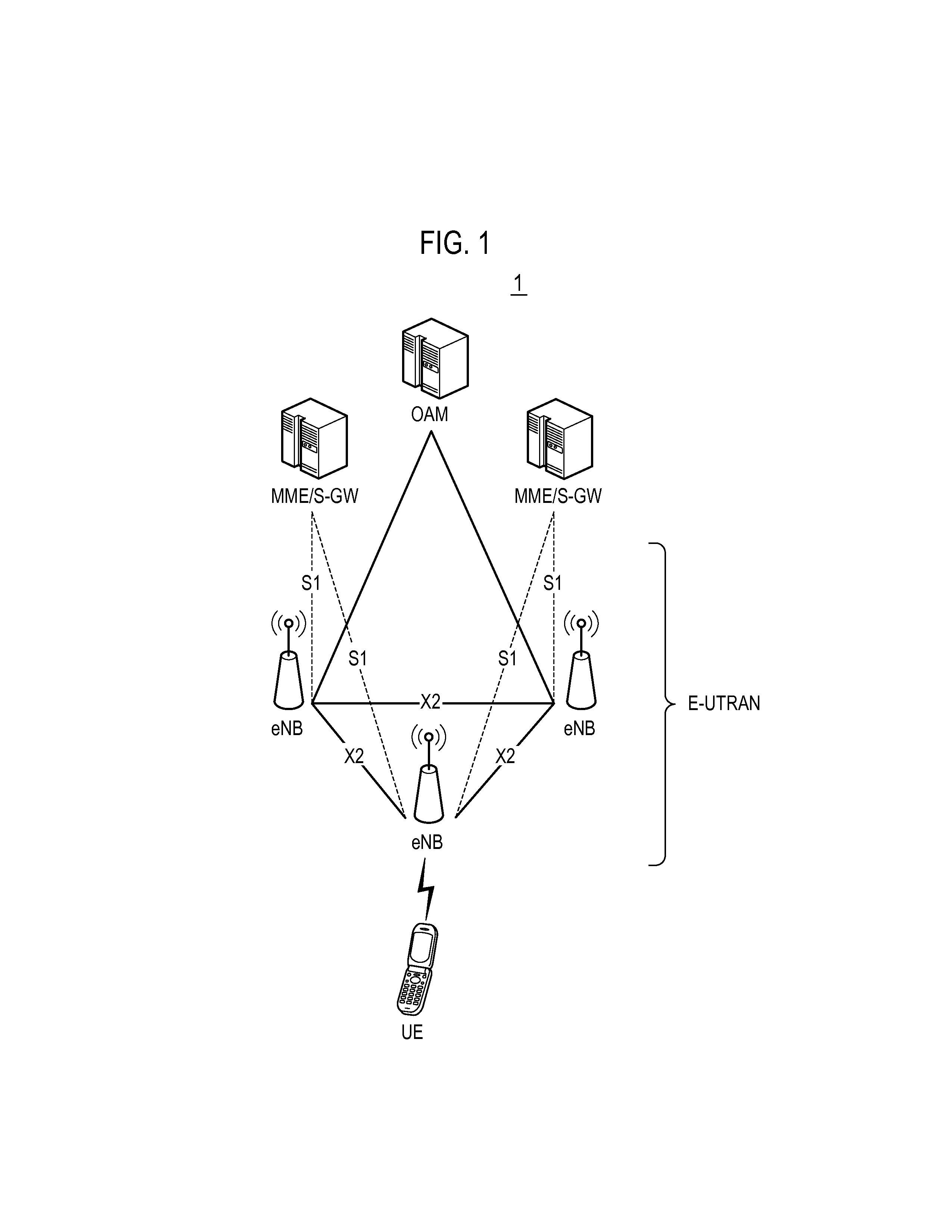
[0052]FIG. 1 is a drawing generally showing a schematic configuration of a mobile communication system 1 according to a first embodiment.
[0053]As shown in FIG. 1, the mobile communication system 1 has a radio terminal UE (User Equipment), a plurality of radio base stations eNB (evolved Node-B), a maintenance and monitoring device OAM (Operation and Maintenance), and a plurality of mobility management devices MME (Mobility Management Entity) / a gateway device S-GW (Serving Gateway).
[0054]The plurality of radio base stations eNB configures E-UTRAN (Evolved-UMTS Terrestrial Radio Access Network). Each radio base station eNB forms a cell which is a co...
second embodiment
(2) Second Embodiment
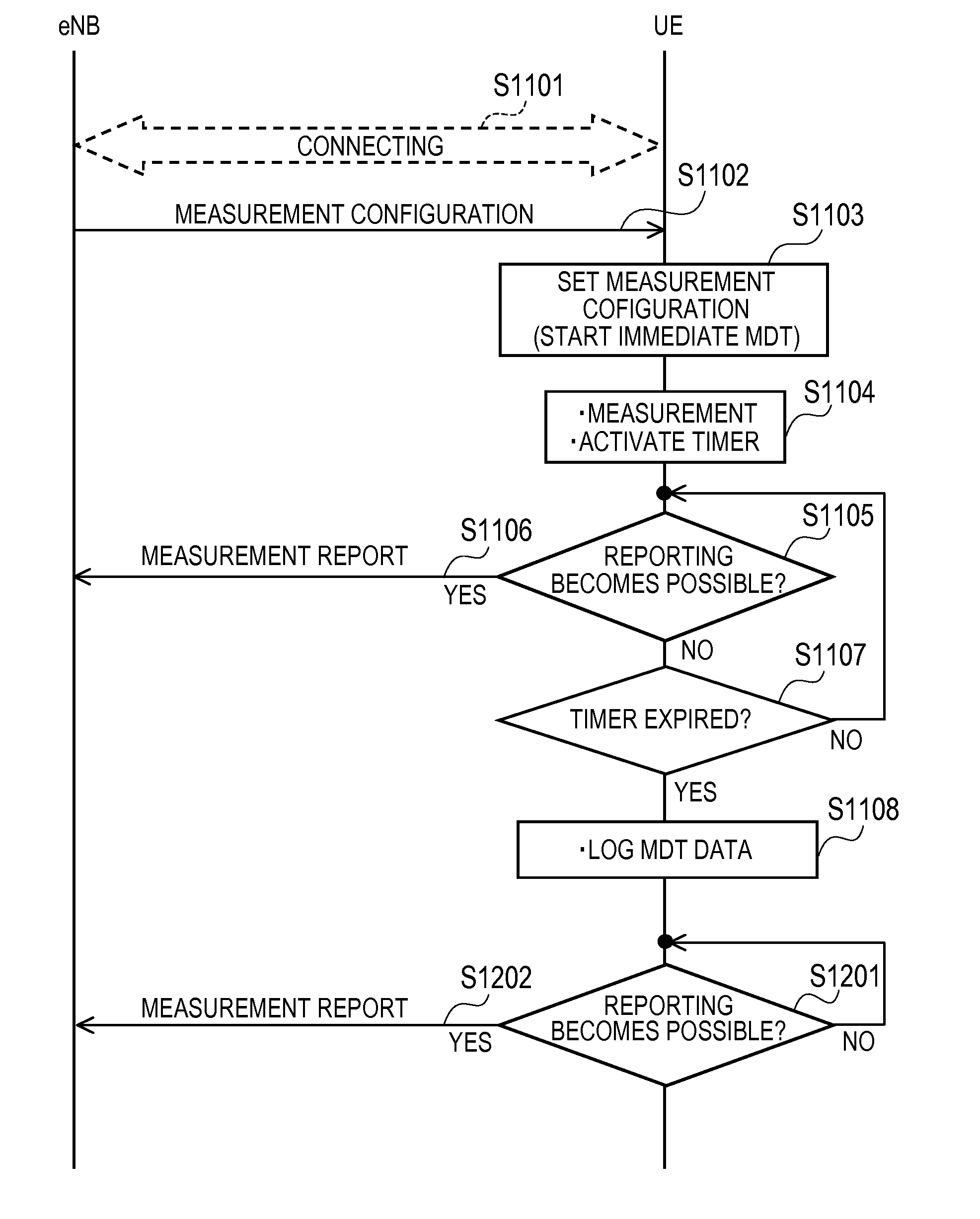
[0095]In the above-described first embodiment, when the measurement result does not become possible to be reported before the timer expires, the radio terminal UE stores the measurement result together with the location information and the time stamp when the timer expired, and performs switching from the Immediate MDT to the Logged MDT in connected.
[0096]In a second embodiment, when a measurement result does not become possible to be reported before a timer expires, a radio terminal UE stores the measurement result together with location information and a time stamp when the timer expired, and, thereafter, when the measurement result becomes possible to be reported, the radio terminal UE reports the measurement result together with the location information and the time stamp.
[0097]FIG. 6 is a sequence diagram showing a radio measurement collection method according to the second embodiment.
[0098]As shown in FIG. 6, at step S1101, the radio terminal UE is in a co...
third embodiment
(3) Third Embodiment
[0108]In the above-described first embodiment, when the measurement report does not become possible to be reported before the timer expires, the radio terminal UE stores the measurement result together with the location information and the time stamp when the timer expired, and performs switching from the Immediate MDT to the Logged MDT in connected. Also, in the above-described second embodiment, when the measurement result does not become possible before the timer expires, the radio terminal UE stores the measurement result together with the location information and the time stamp when the timer expired and reports the measurement result together with the location information and the time stamp when reporting becomes possible.
[0109]In a third embodiment, when a measurement result does not become possible to be reported before a timer expires, a radio terminal UE deletes the measurement result and location information when the timer expired.
[0110]FIG. 7 is a seq...
PUM
 Abstract
Description
Claims
Application Information
 - R&D
- Intellectual Property
- Life Sciences
- Materials
- Tech Scout
- Unparalleled Data Quality
- Higher Quality Content
- 60% Fewer Hallucinations
Browse by: Latest US Patents, China's latest patents, Technical Efficacy Thesaurus, Application Domain, Technology Topic, Popular Technical Reports.
© 2025 PatSnap. All rights reserved.Legal|Privacy policy|Modern Slavery Act Transparency Statement|Sitemap|About US| Contact US: help@patsnap.com


