Processing signals acquired during guided wave testing

Active Publication Date: 2013-07-11
GUIDED ULTRASONICS LTD
View PDF3 Cites 6 Cited by
  • Summary
  • Abstract
  • Description
  • Claims
  • Application Information

AI Technical Summary

Benefits of technology

[0017]The present invention seeks to provide a method of determining the reflection coefficient or a parameter suitable for calibrating a guided wave test

Problems solved by technology

The methods of calibration currently available tend either to lack accuracy or to make assumptions which cannot be safely assumed to be true.
Weld reinforcement dimensions are not standardised and the dimensions of the weld reinforcement, the root and the width of the weld can vary significantly even within the same pipeline, resulting in a calibration error when assuming a certain size of reflection.
However, the dimensions of the weld can vary significantly even within the same girth weld, particularly reinforcement and root penetration, and can therefore lead to significant errors in the calibration.
If the girth weld is defective in a way which influences the size of the reflection, then any calibration which assumes a certain size of reflection or which involves directly measuring the girth weld reinforcement and width can lead to a significant error in sizing.
An example of an in-service defect in a girth weld which can lead such a calibration error is weld root corrosion.
An example of a manufacturing defect is insufficient root-penetration.
Calibration using girth welds cannot be used when there are no girth welds within the range of the guided wave test, when they are not acce

Method used


Image

  • Processing signals acquired during guided wave testing
  • Processing signals acquired during guided wave testing
  • Processing signals acquired during guided wave testing

Examples


Example

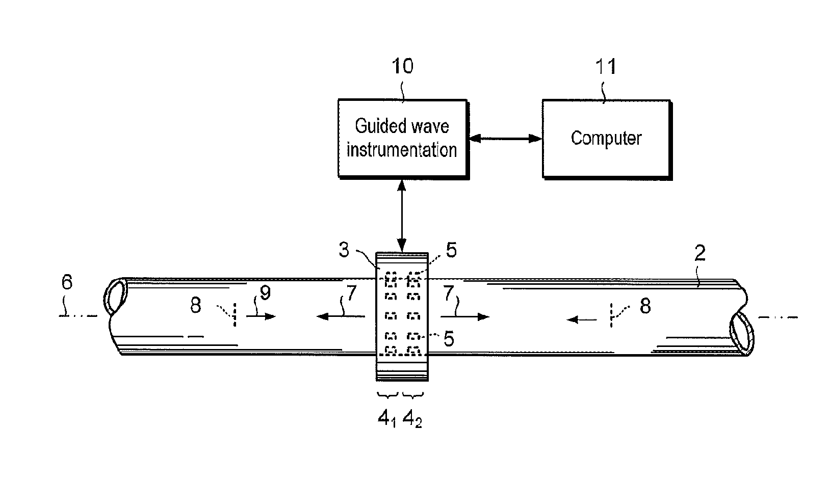
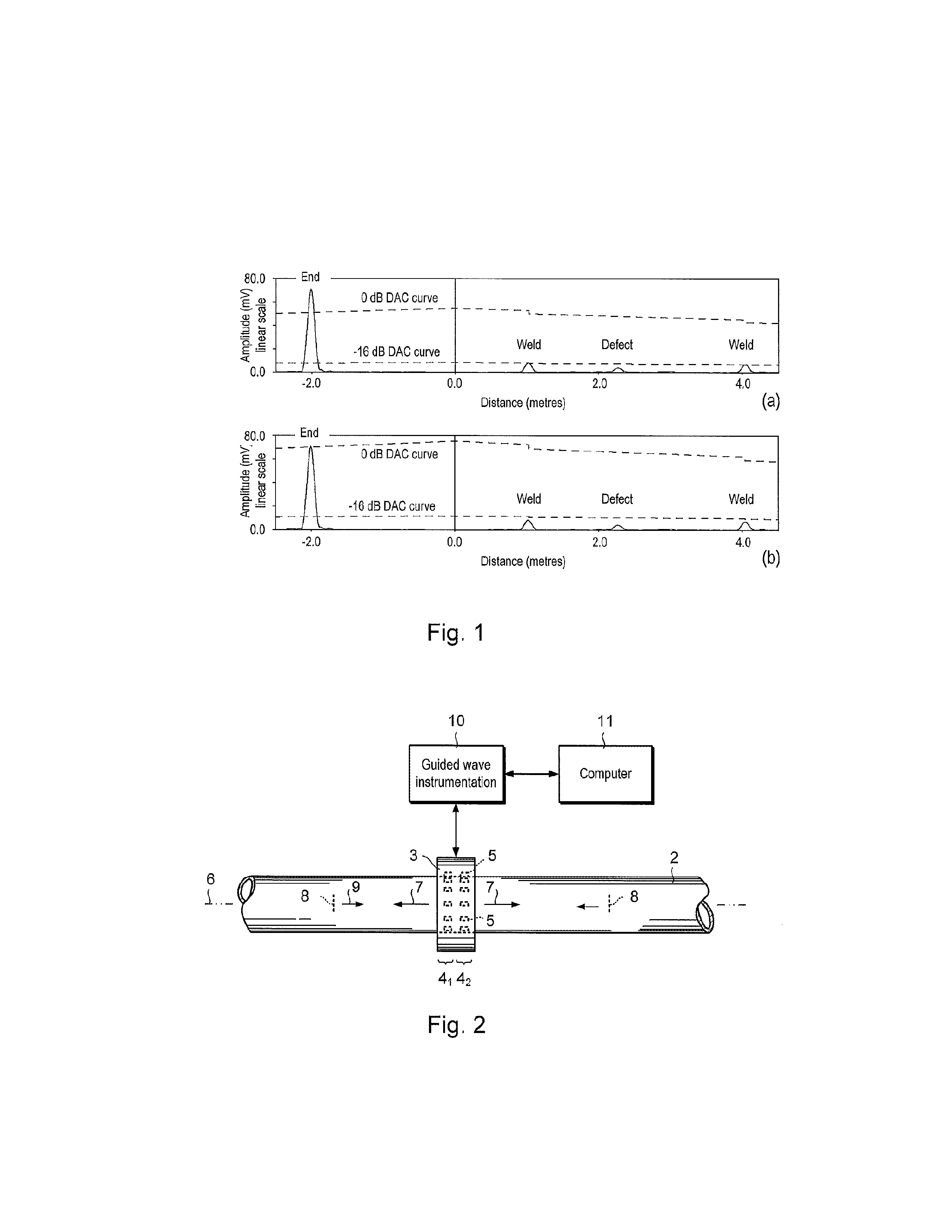
[0086]Referring to FIG. 2, a system 1 for inspecting a pipe 2 or other elongate member using guided waves is shown. The system 1 includes a transducer ring 3 having at least two rows or sets 41, 42 of transmitting / receiving transducers 5 spaced apart along the longitudinal axis 6 of the pipe 2. In this example, the transducers 5 are discrete, piezoelectric transducers and the transducers 5 in each set 41, 42 are angularly-spaced around the perimeter of the pipe 2 in a similar way to that described in WO 96 12951 A ibid. However, the transducers 5 need not be discrete and other types of transducers can be used.

[0087]The transducer ring 3 is used to excite guided waves 7 in the form of pulses in the pipe 2 at a propagating frequency, typically in the range between about 10 and about 500 kHz, which propagate along the pipe 2. Discontinuities 8, such as defects, welds or other types of interface (herein collectively referred to as “reflectors”) reflect some or all of the outgoing waves ...


PUM


Abstract

Processing signals acquired during guided wave testing A method of processing signals acquired during guided wave testing of an elongate member (2), such as a pipe, in which at least one guided wave (7) is generated in the elongate member, the at least one guided wave is reflected by reflectors (8) in the elongate member and reflected guided waves (9) are detected. The method comprises determining at least one reflection coefficient or a parameter for calibrating a guide wave test in dependence upon reflections from the reflectors which include at least one multiple reflection. The reflections may include a single reflection from a first reflector, a single reflection from a second reflector and a multiple reflection from the first and second reflectors.

Description

FIELD OF THE INVENTION[0001]The present invention relates to a method of and apparatus for processing signals acquired during guided wave testing of an elongate member, such as a pipe, tube, rod or rail. The present invention also relates to a method of and apparatus for guided wave testing of an elongate member.BACKGROUND[0002]Guided wave testing is a non-destructive testing method used to inspect pipework for discontinuities in the wall of a pipe, such as corrosion-type defects and cracks. Reference is made to WO 96 12951 A which describes an apparatus and method for inspecting elongate members and which is incorporated herein by reference.[0003]As with most non-destructive testing methods, a guided wave system typically requires calibration so that the received signal amplitudes can be related accurately to the reflection coefficient of the discontinuity. The reflection coefficient is, among other variables such as guided wave wavelength and mode, related to the shape and dimensi...

Claims


Application Information

Patent Timeline
IPC IPC(8): G01N29/44
CPCG01N29/043G01N29/11G01N29/4463G01N29/44G01N2291/0425G01N2291/044G01N2291/2634G01N29/46G01N29/30G01N29/4445G01N29/4454
Inventor VOGT, THOMAS
Owner GUIDED ULTRASONICS LTD
Why Eureka
Try Eureka