
Gas turbine exhaust diffuser having plasma actuator

a technology of plasma actuator and exhaust diffuser, which is applied in the direction of engine control, machine/engine, stators, etc., can solve the problems of pressure loss and general consumption of exhaust diffuser spa

Inactive Publication Date: 2013-07-18
GENERAL ELECTRIC CO
View PDF15 Cites 10 Cited by
  • Summary
  • Abstract
  • Description
  • Claims
  • Application Information

AI Technical Summary

Benefits of technology

The invention is a gas turbine with a plasma actuator. The turbine releases exhaust gas, which is then received by an exhaust diffuser. The diffuser has a wall that the plasma actuator produces plasma along. The technical effect of this invention is that it improves the efficiency of gas turbines by reducing flow loss and improving flow uniformity.

Problems solved by technology

The exhaust diffuser generally consumes a large amount of space.
If the axial length of the diffuser is not sufficient and is too short, flow separation may occur at the diverging walls of the exhaust diffuser, which results in pressure losses.

Method used


Image

  • Gas turbine exhaust diffuser having plasma actuator
  • Gas turbine exhaust diffuser having plasma actuator
  • Gas turbine exhaust diffuser having plasma actuator

Examples


Embodiment Construction

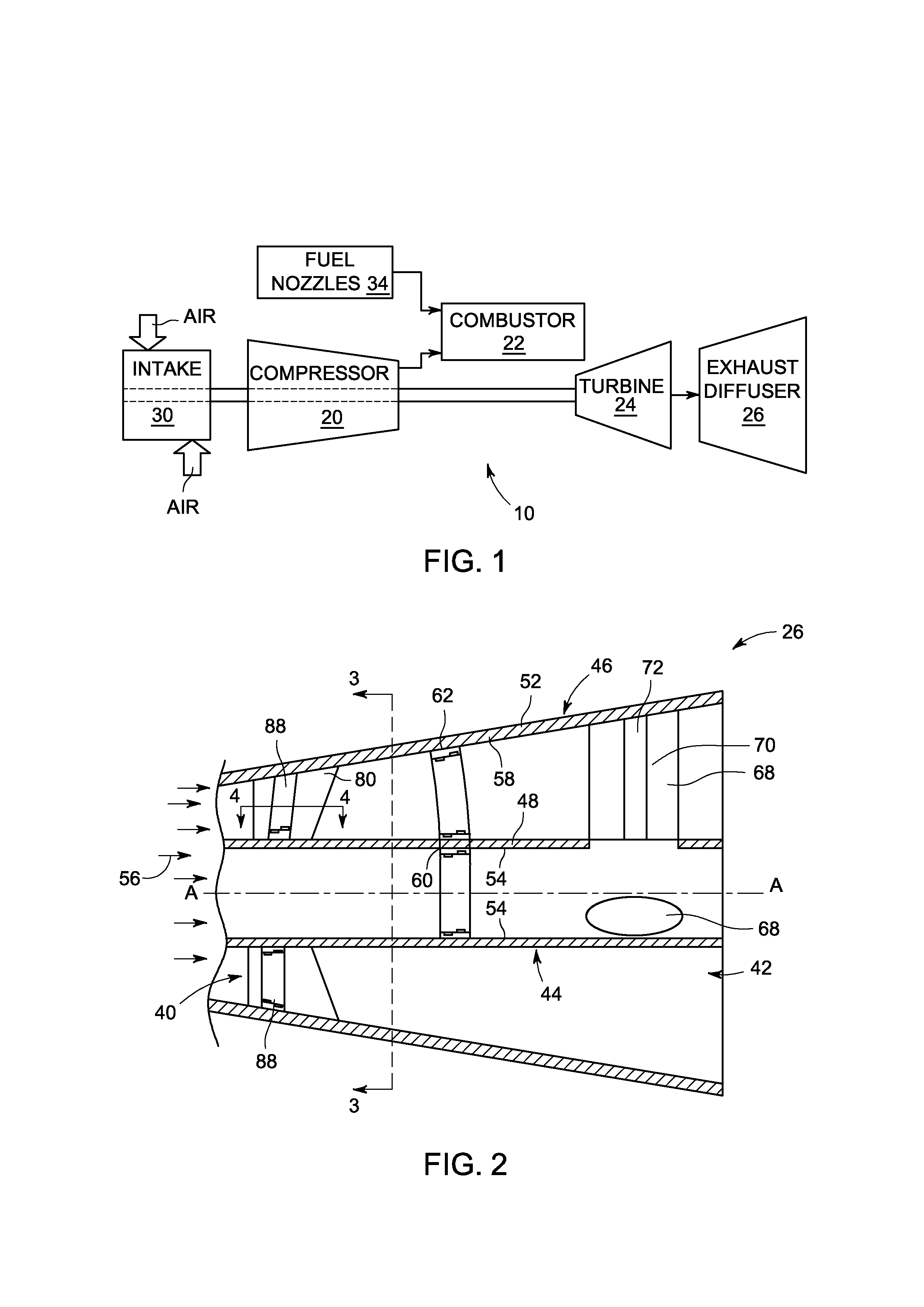
[0013]FIG. 1 illustrates a schematic exemplary power generation system indicated by reference number 10. The power generation system 10 is a gas turbine system having a compressor 20, a combustor 22, a turbine 24, and an exhaust diffuser 26. Air enters the power generation system 10 though an air intake 30 connected to the compressor 20, and is compressed by the compressor 20. The compressed air is then mixed with fuel by a fuel nozzle 34 in a specific ratio for combustion. The combustion generates hot pressurized exhaust gas that drives blades (not shown) that are located within the turbine 24. The exhaust gas is sent from the turbine 24 to the exhaust diffuser 26.

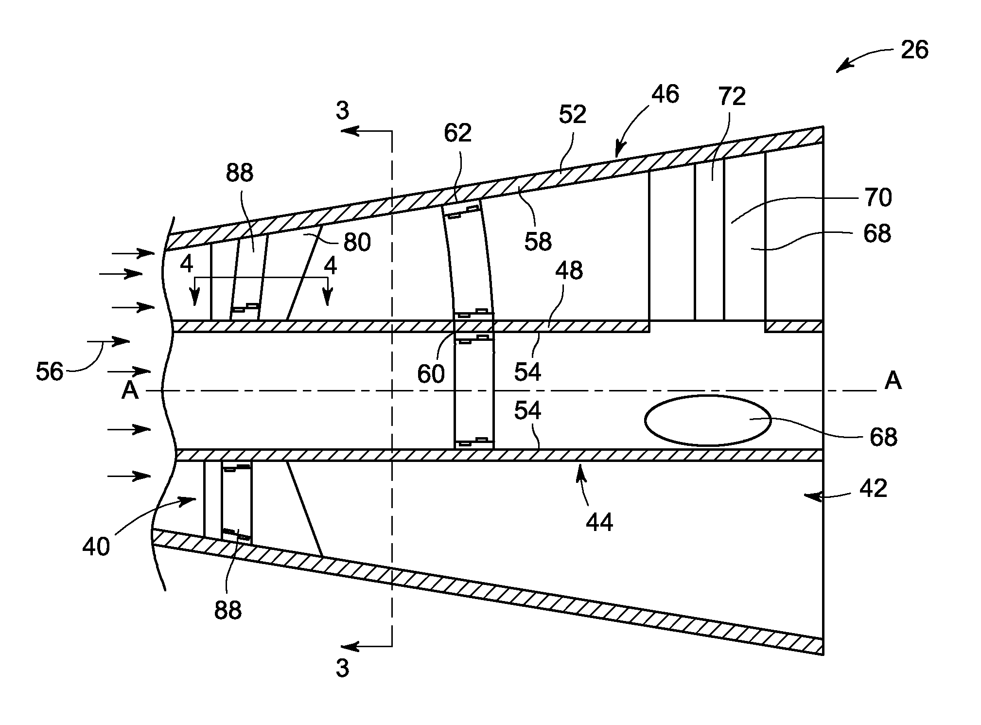
[0014]FIG. 2 is an exemplary illustration of a side view of the exhaust diffuser 26. The exhaust diffuser 26 includes an inlet 40, an outlet 42, an inner diffuser 44 and an outer diffuser 46. The inner diffuser 44 includes an inner wall 48 and the outer diffuser 50 includes an outer wall 52. The inner wall 48 and the oute...


PUM


Abstract

A gas turbine is provided, including a turbine, an exhaust diffuser, and a plasma actuator. The turbine releases an exhaust gas. The exhaust diffuser receives the exhaust gas from the turbine. The exhaust diffuser has an inlet and an outlet, and at least one wall that is disposed between the inlet and the outlet. The plasma actuator produces a plasma along the at least one wall of the diffuser.

Description

BACKGROUND OF THE INVENTION[0001]The subject matter disclosed herein relates to a gas turbine, and more specifically to a gas turbine exhaust diffuser having a plasma actuator for producing a plasma.[0002]Gas turbines generally include a compressor, a combustor, one or more fuel nozzles, a turbine and an exhaust diffuser. Air enters the gas turbine through an air intake and is compressed by the compressor. The compressed air is then mixed with fuel supplied by the fuel nozzles. The air-fuel mixture is supplied to the combustors at a specified ratio for combustion. The combustion generates pressurized exhaust gases, which drive blades of the turbine. An exhaust diffuser may be utilized to improve efficiency of the last stage turbine blade, which is also referred to as a last stage bucket, by decreasing the static pressure at the turbine exit.[0003]The exhaust diffuser generally consumes a large amount of space. The exhaust diffuser includes an inlet and an outlet that are located bet...

Claims


Application Information

Patent Timeline
IPC IPC(8): F01D25/30
CPCF01D9/041F05D2270/172F01D25/162F01D9/065
Inventor SADDOUGHI, SEYED GHOLAMALINANDA, DEEPESH DINESHSADHU, ANTANU
Owner GENERAL ELECTRIC CO
Learn More