

Welding device
- Summary
- Abstract
- Description
- Claims
- Application Information
AI Technical Summary
Benefits of technology
Problems solved by technology
Method used
Image

Examples
first embodiment
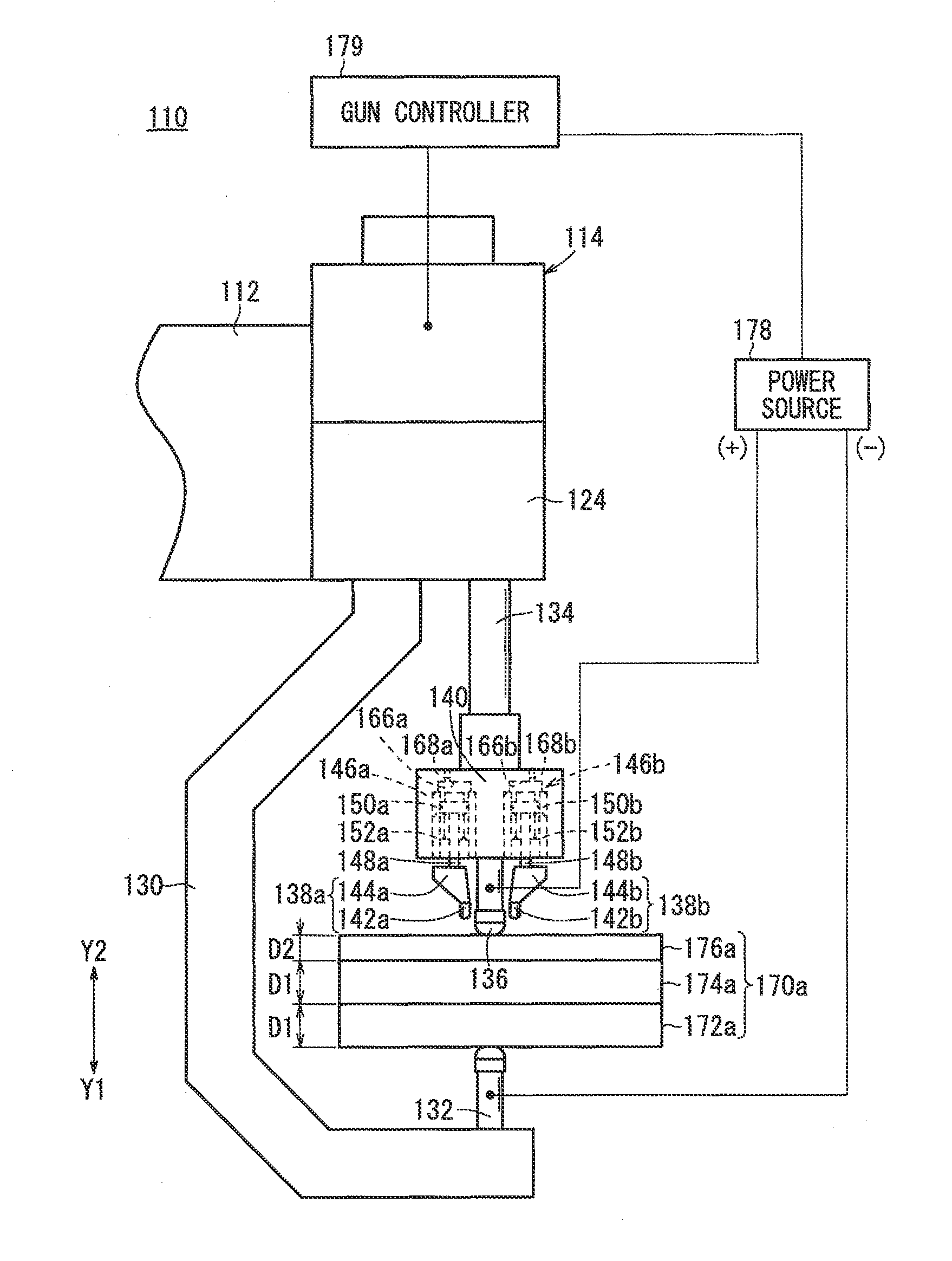
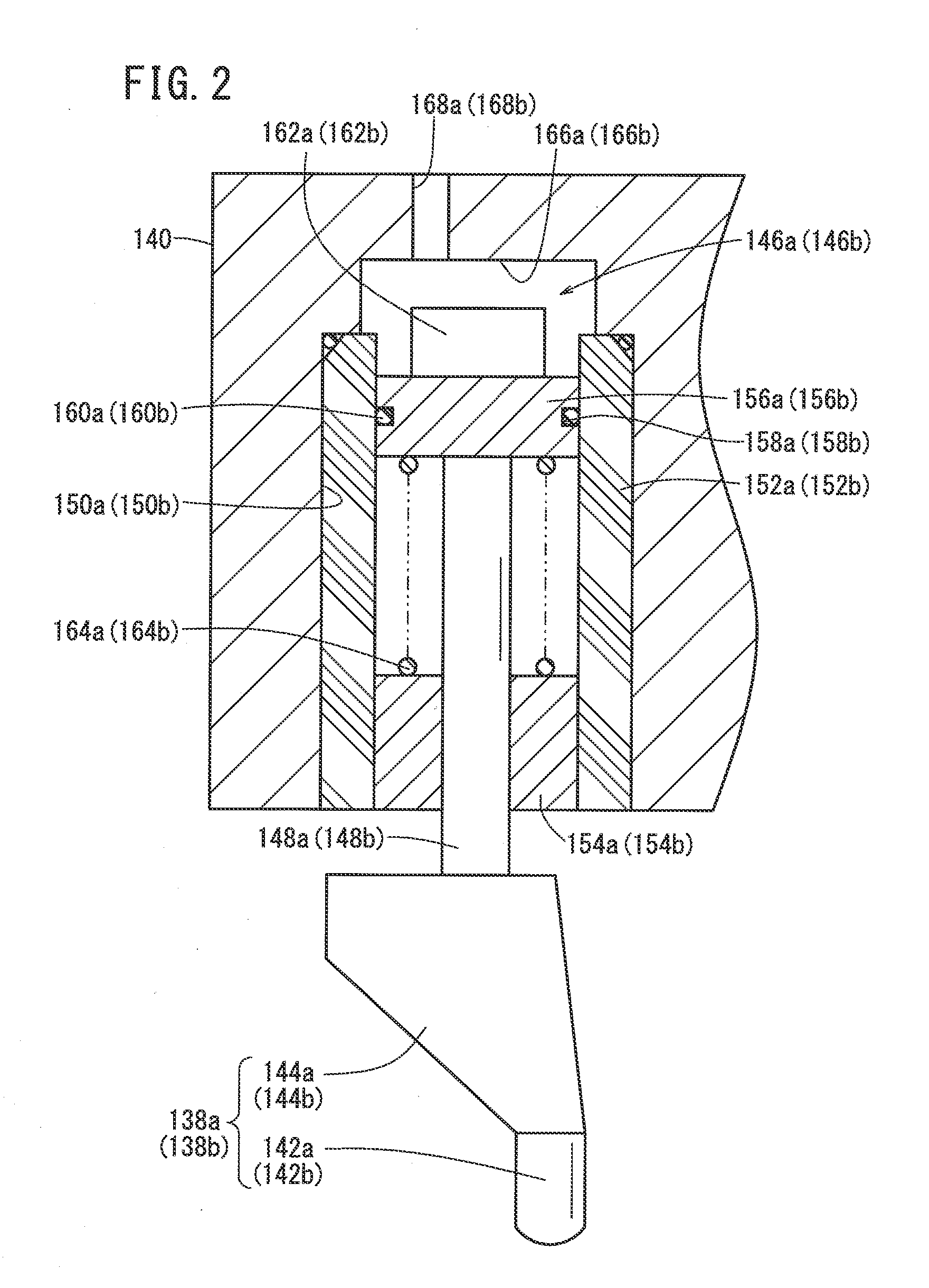
[0115]FIG. 1 is an enlarged view of a spot welding apparatus 110 according to a The spot welding apparatus 110 contains a robot having an arm (not shown) and a welding gun 114 supported on a wrist 112 of the arm.
[0116]The welding gun 114 is a so-called C-type gun having an approximately C-shaped fixed arm 130 under a gun body 124. A lower tip 132 is disposed as a second welding tip on the lower end of the fixed arm 130 in confronting relation to the gun body 124, and extends toward the gun body 124.
[0117]The gun body 124 contains a ball screw mechanism (not shown) for displacing a holder (support) 140 in the vertical direction of FIG. 1. Thus, the ball screw mechanism is a holder (support) displacement mechanism for displacing the holder 140.
[0118]A displacement shaft 134 projects from the gun body 124 and extends toward the lower tip 132, and is displaced by a ball screw in the ball screw mechanism in the vertical direction (arrow Y2 or Y1 direction) of FIG. 1. The ball screw is r...
second embodiment
[0174]The main part of the spot welding apparatus of the second embodiment is basically constructed as described above. Operations and advantages of the apparatus will be described below.
[0175]In a spot welding method using the spot welding apparatus for spot welding the stacked body 170a, first the robot moves the welding gun to position the stacked body 170a between the upper tip 136 and the lower tip 132 in the same manner as the first embodiment. Thereafter, the upper tip 136 and the lower tip 132 are moved close to each other, whereby the stacked body 170a is gripped therebetween.
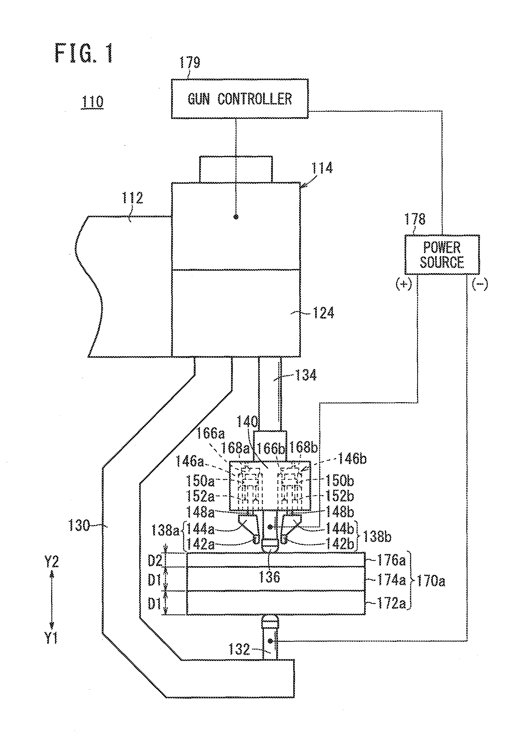
[0176]Before, at the same time as, or after the gripping, the compressed air is supplied to the rooms 166a, 166b through the air supply / discharge passages 168a, 168b (see FIGS. 1 and 2). The pistons 156a, 156b and the piston rods 148a, 148b are moved downward by the compressed air, so that the auxiliary electrodes 190a, 190b are lowered toward the stacked body 170a in the arrow Y1 direction. Consequent...
third embodiment
[0228]A welding apparatus (spot welding apparatus) will be described below.
[0229]FIG. 25 is a schematic side view of a spot welding apparatus 310 according to a third embodiment, and FIG. 26 is an enlarged front view of a main part thereof. The spot welding apparatus 310 contains a robot having an arm (not shown) and a welding gun 314 supported on a wrist 312 of the arm.
[0230]The welding gun 314 is a so-called C-type gun having an approximately C-shaped fixed arm 318 under a gun body 316. A lower tip 320 is disposed as a second welding tip on the lower end of the fixed arm 318, and extends toward the gun body 316.
[0231]The gun body 316 contains a ball screw mechanism (not shown) for displacing, in the vertical direction (the arrow Y2 or Y1 direction) of FIGS. 25 and 26, a holder 324 having an upper tip 322 as a first welding tip. Specifically, the holder 324 is disposed on the end of a displacement shaft 326, which projects from the gun body 316 and extends toward the lower tip 320...
PUM
| Property | Measurement | Unit |
|---|---|---|
| Force | aaaaa | aaaaa |
| Polarity | aaaaa | aaaaa |
| Current | aaaaa | aaaaa |
Abstract
Description
Claims
Application Information