
Gripper with force-multiplying mechanism

Active Publication Date: 2013-07-18
PHD
View PDF12 Cites 18 Cited by
  • Summary
  • Abstract
  • Description
  • Claims
  • Application Information

AI Technical Summary

Benefits of technology

The present invention is about a gripper that uses a force-multiplying mechanism to increase the gripping force on a workpiece during operation. This results in a more efficient gripping force over reduced jaw travel. The gripper is fluid actuated and includes a jaw assembly, a cylinder, a piston, and a piston rod with a force-multiplying mechanism interconnected between them. The force-multiplying mechanism adds a mechanical force to the jaw assembly to increase the gripping force on the workpiece. This results in improved holding power and efficiency of the gripper.

Problems solved by technology

Typically, increasing gripping force increases the size of the motor or piston which increases the weight and physical size of the gripper.

Method used


Image

  • Gripper with force-multiplying mechanism
  • Gripper with force-multiplying mechanism
  • Gripper with force-multiplying mechanism

Examples


Embodiment Construction

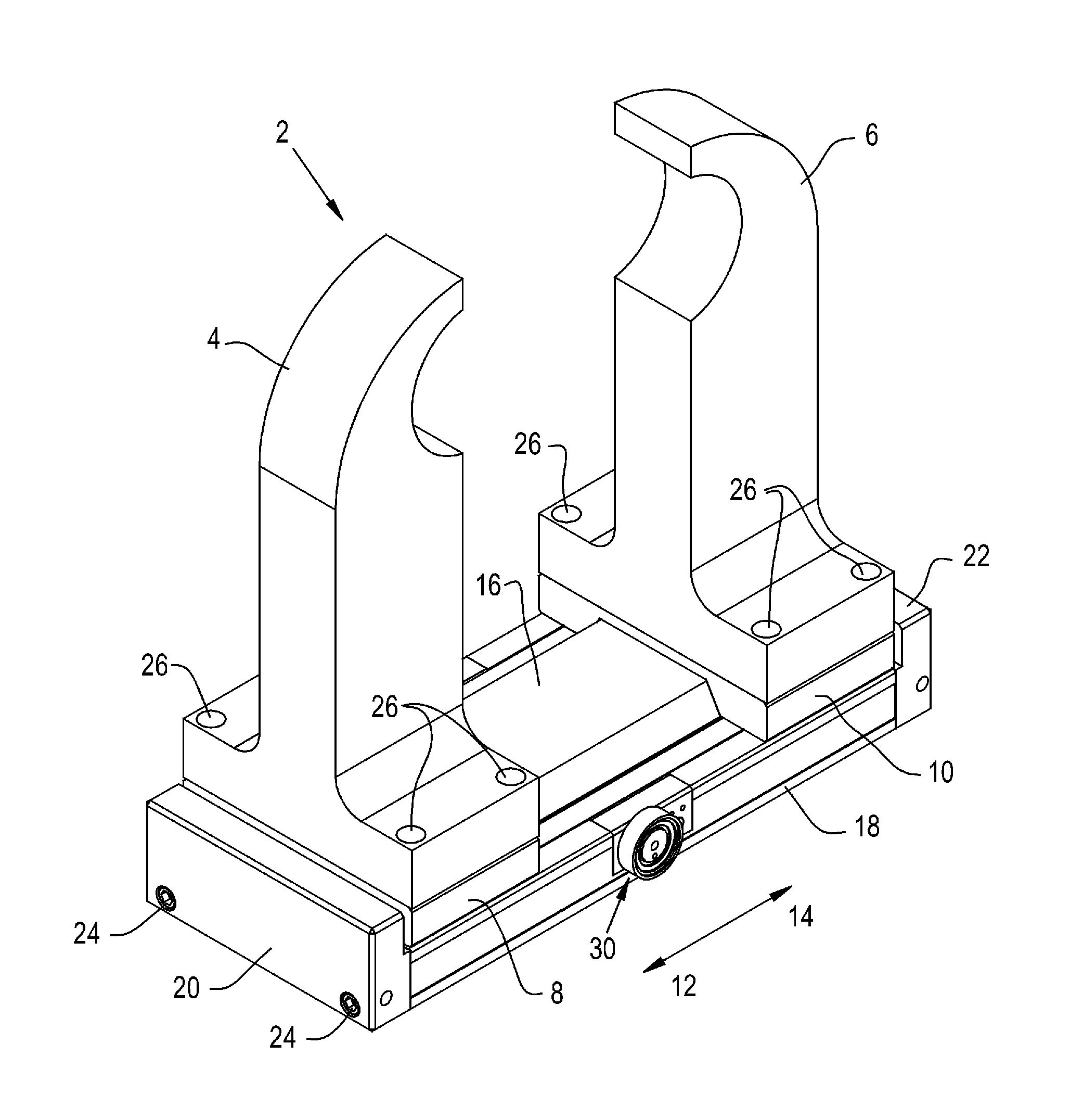
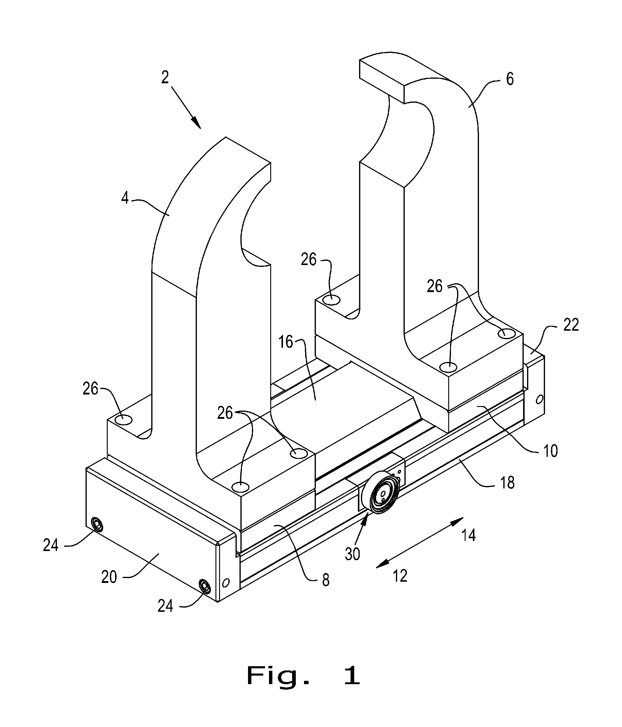
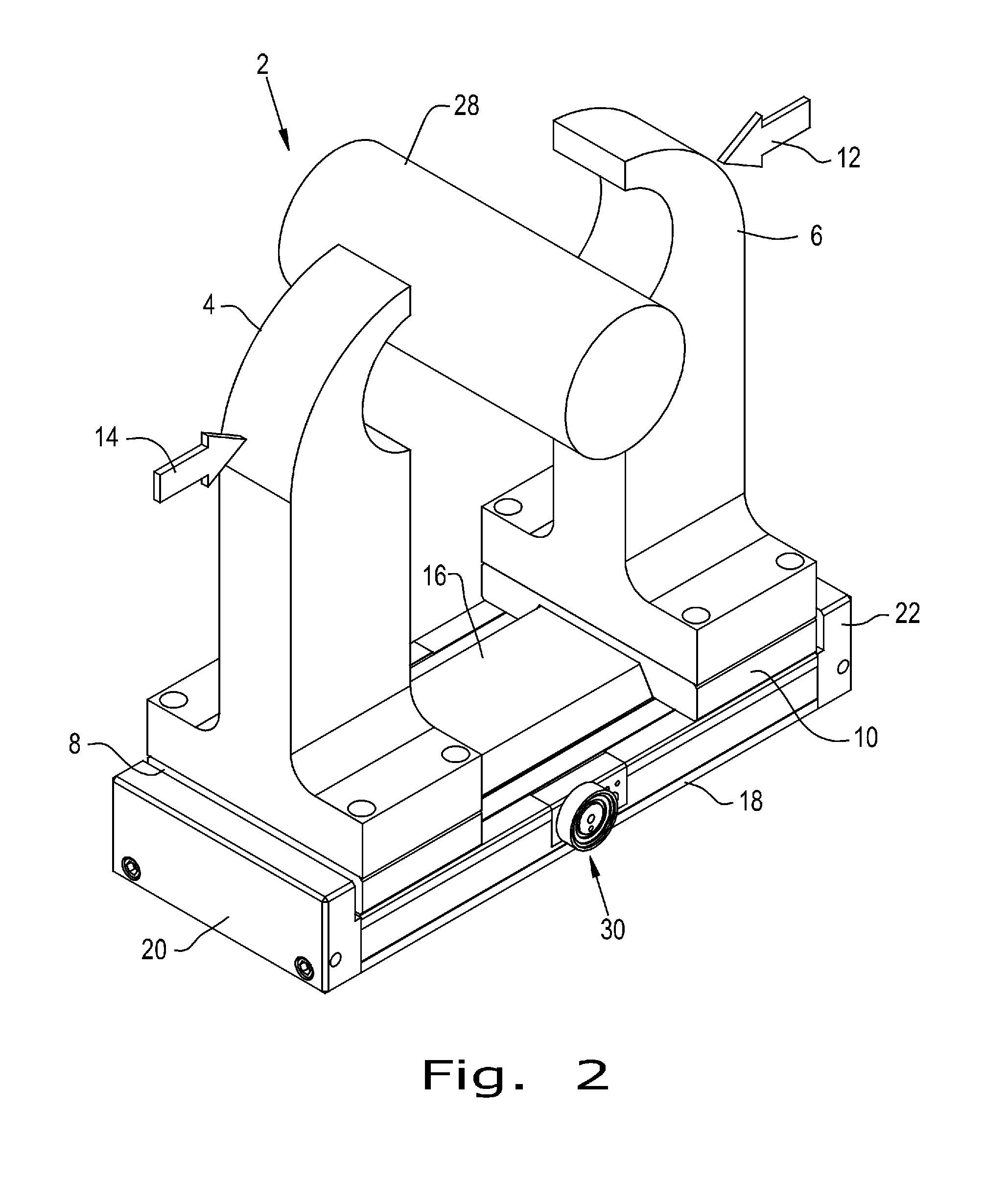
[0029]Referring now to the drawings, and more particularly to FIG. 1, there is shown a gripper 2 that includes a perspective view of a force-multiplying system of the present invention. Gripper 2 includes jaw arms 4 and 6 each attached to a jaw bridge 8 and 10, respectively. Bridges 8 and 10 are slideable in directions 12 and 14 along cover 16. Jaw bridges 8 and 10 are also supported by plate 18 capped by end plates 20 and 22. Fasteners 24 attach end plates 20 and 22 to each respective end of plate 18. Similarly, fasteners 26 illustratively attach jaw arms 4 and 6 to their respective bridges 8 and 10. It is appreciated that jaw arms 4 and 6 may be of any variety of configurations to hold a desired workpiece. The illustrative design of arms 4 and 6 in this embodiment demonstrates their ability to hold a tubular workpiece such as workpiece 28 shown in FIG. 2. A brake assembly 30 is configured to decelerate a moving jaw to rest and hold a stopped jaw in a stationary position. This may ...


PUM


Abstract

A gripper for gripping a workpiece includes a jaw assembly having an actuator with a housing and an elongate member axially slidably movable within the housing. A force-multiplying mechanism is interconnected between the elongate member and the housing. The force-multiplying mechanism is configured to add a mechanical force to the jaw assembly and thereby increase a gripping force on the workpiece during operation of the gripper.

Description

CROSS REFERENCE TO RELATED APPLICATIONS[0001]This is a non-provisional application based upon U.S. provisional patent application Ser. No. 61 / 546,656, entitled “GRIPPER WITH FORCE-MULTIPLYING MECHANISM”, filed Sep. 13, 2011, which is incorporated herein by reference.BACKGROUND OF THE INVENTION[0002]1. Field of the Invention[0003]The present invention relates to grippers for gripping a workpiece.[0004]2. Description of the Related Art[0005]Grippers are mechanical devices characterized by one or more jaws that move together or apart by motive force typically from an electric motor or pneumatic piston. Once moved into a position of contact with the gripped workpiece, the jaws produce a gripping force against the workpiece. It is often desirable for the gripper to provide as large a gripping force as possible while also possessing a minimum weight and physical size. Typically, increasing gripping force increases the size of the motor or piston which increases the weight and physical siz...

Claims


Application Information

Patent Timeline
IPC IPC(8): B66C1/42B25J15/02
CPCB25J15/026B25B1/02B25B1/20B25B1/18B25B1/06
Inventor WILLIAMS, MATTHEW R.NULL, LYLE A.
Owner PHD
Learn More