Electric Motor

a technology of electric motors and motors, applied in the direction of electrical apparatus, control systems, synchronous machines with stationary armatures and rotating magnets, etc., can solve the problems of increasing the reliability of the motor and the power output of the motor, and achieve the effect of easy cooling, easy cooling of the motor and easy increasing the power of the motor

Inactive Publication Date: 2013-07-18
NADEAU ERIC
View PDF9 Cites 0 Cited by
  • Summary
  • Abstract
  • Description
  • Claims
  • Application Information

AI Technical Summary

Benefits of technology

[0009]Advantageously, the presence of the two end of rotors maximizes the efficiency of the proposed motor as coil magnetic field leaks outside of the motor are minimized.
[0010]In some embodiments of the invention, the coils of adjacent stators are circumferentially offset from each other. In these embodiments, having rotors with aligned permanent magnets allows for relatively easily controlling the sequence of powering of the adjacent stators. In addition, this structure creates a multiphase motor that increases the reliability of the motor as a failure of one of the stators only slightly decreases the power output by the motor.
[0011]In some embodiments of the invention, the coils are coreless made out of two coil sections disposed substantially adjacent to each other with their input and output wires at the middle of the coils. This configuration of the coils facilitates the wiring of the proposed motor and allows for selectively powering the two coil sections in series or in parallel. In addition, coreless coils eliminate polarization losses created in ferromagnetic cores.
[0013]Due to its high-efficiency, the proposed motor is relatively easily cooled, and the structure of the motor allows for easily cool the motor using a gas or a liquid.
[0014]The modular nature of the proposed motor allows for relatively easily increasing the power of the motor by increasing the number of rotors and stators. In addition, the use of a number of substantially identical modules creates economies of scale and ease of assembly.
[0017]In applications in which two wheels are connected to a single motor, having two axles in the motor, each connected to a respective one of the first and second section rotors, creates an independence between the two wheels which can then have a difference in rotation speed without requiring a differential. The magnetic coupling provides limited slip between the two motor sections.

Problems solved by technology

In addition, this structure creates a multiphase motor that increases the reliability of the motor as a failure of one of the stators only slightly decreases the power output by the motor.

Method used


Image

  • Electric Motor
  • Electric Motor
  • Electric Motor

Examples


Embodiment Construction

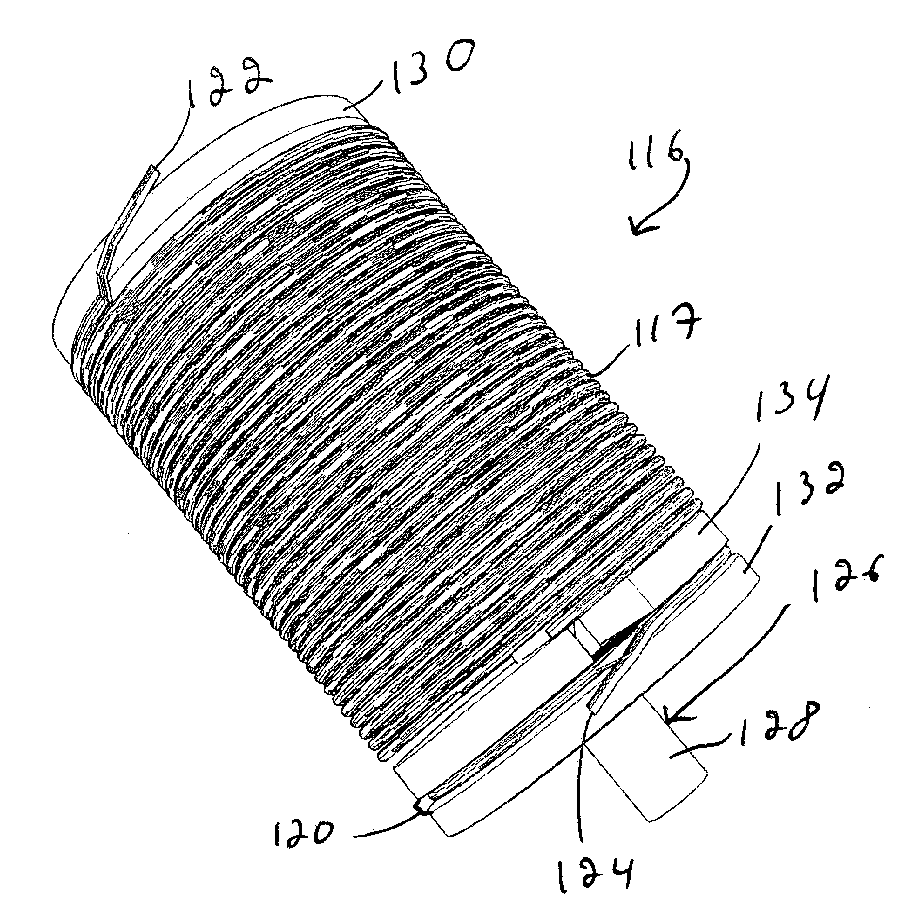
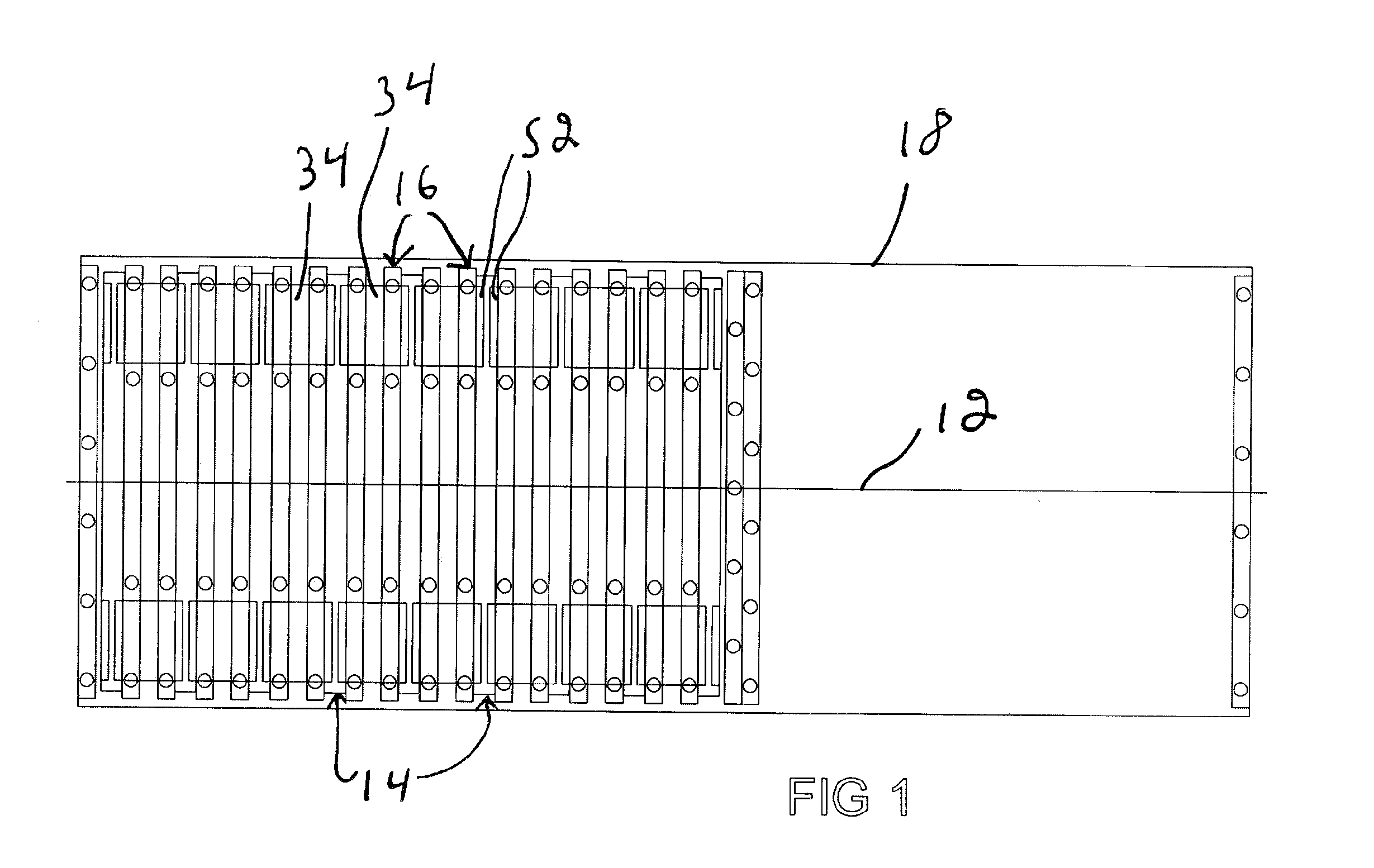
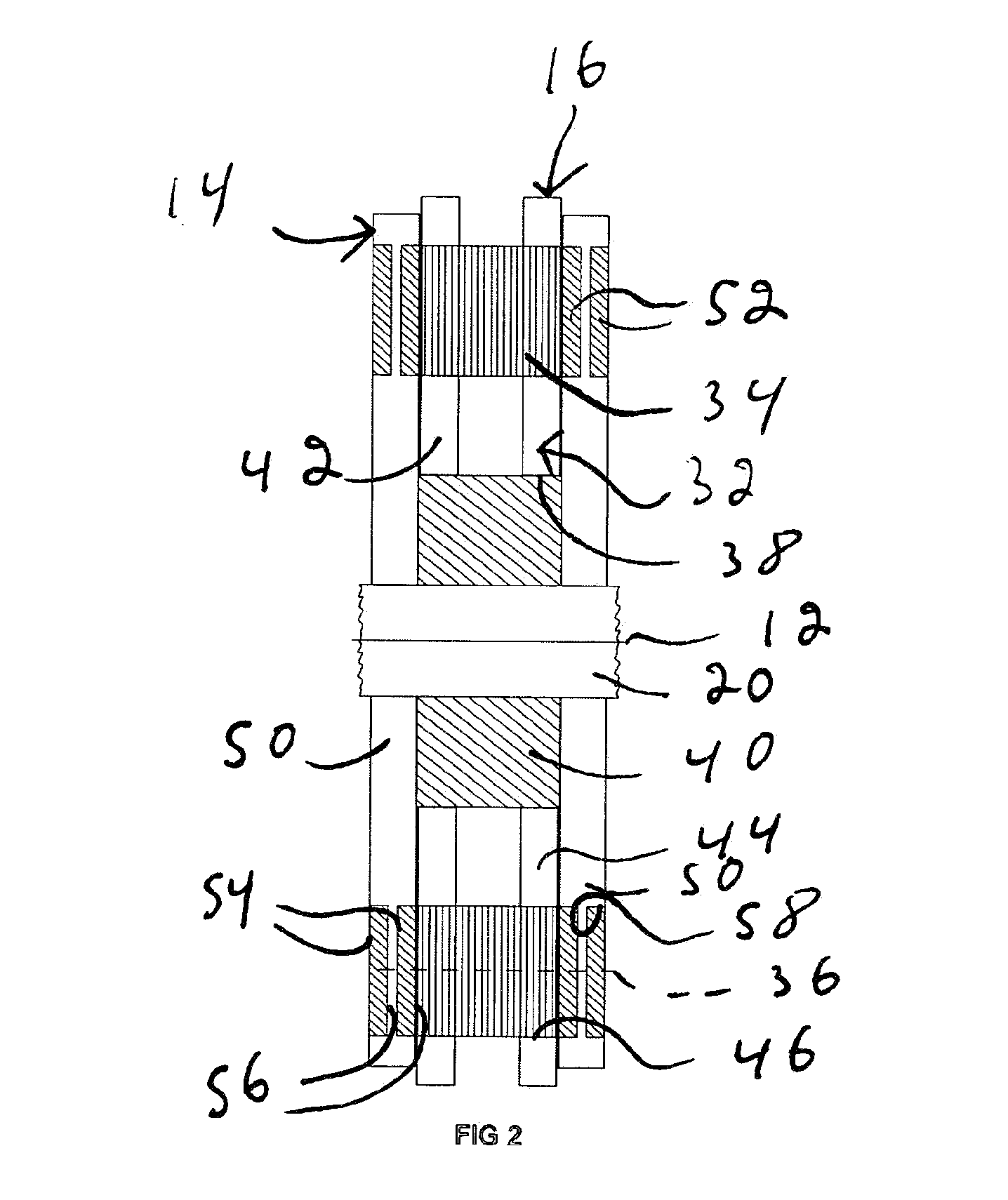
[0032]With reference to FIG. 1, there is shown and electric motor 10 in accordance with an embodiment of the invention. The electric motor 10 defines a motor longitudinal axis 12. The electric motor 10 includes a plurality of substantially coaxial stators 16. The stators 16 are substantially axially spaced apart from each other. The electric motor 10 also includes a plurality of substantially coaxial rotors 14. The rotors 14 are divided into internal rotors 14 and end rotors 14. Each of the internal rotors 14 is inserted between two of the stators 16. The stators 16 and the internal rotors 14 are located between the two end rotors 14. The rotors 14 and the stators 16 are mounted inside a casing 18. An axle 20 is mechanically coupled to at least the one of the end rotors 14 and at least one of the internal rotors 14 so that the rotors 14 that are mechanically coupled to the axle 20 are substantially jointly rotatable therewith about the motor longitudinal axis 12. For example, the ro...


PUM


Abstract

An electric motor, comprising motor first and second sections, said motor first and second sections including each a rotor and a stator rotatable relative to each other, said stators including each a plurality of coils disposed in a substantially annular configuration therearound, said rotors including each a plurality of permanent magnets disposed in a substantially annular configuration therearound; said rotors being substantially coaxial and facing each other, said rotors being rotatable independently from each other; said rotors being magnetically coupled to each other so that a rotation of a first one of said rotors causes a rotation of the other one said rotors.

Description

[0001]This application claims priority from U.S. Provisional Patent Application Ser. No. 61 / 193,982 filed Jan. 15, 2009.FIELD OF THE INVENTION[0002]The present invention relates generally to electric motors.BACKGROUND[0003]There is an increasing interest in the automotive industry for electric motor propulsion. Since automotive applications are by definition mobile, the motors used in such applications are powered by batteries. Battery power causes numerous constraints to electric vehicles. For example, because of the relatively low power density of batteries, there is a need to have relatively efficient electric motors in these applications. Also, high power density batteries are relatively costly, and, in some applications, represent a significant portion of the manufacturing cost of an electric vehicle. Therefore, using relatively sophisticated electric motors that would be more efficient could result in lower cost vehicles, even if these motors are more expensive because of this...

Claims


Application Information

Patent Timeline
Patent Type & Authority Applications(United States)
IPC IPC(8): H02K16/00
CPCH02K21/24H02K16/00H02P25/18
Inventor NADEAU, ERIC
Owner NADEAU ERIC
Why Eureka
Try Eureka