Digital load control system providing power and communication via existing power wiring

a load control system and digital technology, applied in the field of two-wire load control, can solve the problems of inability to connect to the neutral side of the ac power source in the wallbox where the mechanical switch is located, requiring subsequent repair, and high cost of running additional wiring

Active Publication Date: 2013-07-18
LUTRON TECH CO LLC
View PDF3 Cites 191 Cited by
  • Summary
  • Abstract
  • Description
  • Claims
  • Application Information

AI Technical Summary

Benefits of technology

[0021]Rather than modulating high-frequency digital messages or pulses onto the AC mains line voltage, the controller generates a phase-control voltage having a variable timing edge (i.e., phase angle). Specifically, the controller transmits digital messages to the load control device by modulating the timing edges of the phase-control voltage relative to a reference edge, i.e., digital information is encoded in the timing between the edges. The timing of the edges of the phase-control voltage can be controlled precisely by the controller and detected reliably by the load control device, which does not require a zero-crossing detector to detect the timing edges of the phase-control voltage. Since the controller generates a phase-control voltage for communicating digital information to the load control device, the el

Problems solved by technology

Moreover, a neutral wire connection coupled to the neutral side of the AC power source may not be available in the wallbox where the mechanical switch is located.
Running additional wiring can be very expensive, due to the cost of the additional electrical wiring as well as the cost of installation.
In addition, if the pre-existing wiring from the mechanical switch to the ballast runs behind a fixed ceiling or wall (e.g., one comprising plaster or expensive hardwood), the electrician may need to breach the ceiling or wall to install the new electrical wiring, which will thus require subsequent repair.
A further complication may arise when the existing ceiling contains asbestos.
The process is expensive and time consuming.
Therefore, the prior art three-wire dimming ballast does not work well in retrofit installations as described above because the ballast requires two electrical connections—not one—between the dimmer switch and the ballast (i.e., the switched-hot voltage and the dimmed-hot voltage) and the dimmer switch requires connection to a neutral wire coupled to the neutral side of the AC power source in addition to the hot wire.
However, the dimmer switch is only able to control the two-wire dimming ballasts in unison since each ballast receives the identical phase-control voltage from the dimmer switch.
The dimmer switch cannot individually control the intensities of each of the ballasts coupled to the dimmer switch.
The prior art digital dimming ballasts require that the wired digital communication link is coupled to each of the ballasts—in addition to the power wiring—and thus are not well suited to retrofit installations, where the digital dimming ballasts are replacing non-dimming ballasts.
However, such power-line carrier communication systems have many disadvantages that have prevented the systems from enjoying wide commercial success.
Typically, the control devices of power-line carrier communication systems require connections to both the hot side and the neutral side of the AC power source, which connections may not both be available in the electrical wallboxes of a retrofit installation.
In addition,

Method used


Image

  • Digital load control system providing power and communication via existing power wiring
  • Digital load control system providing power and communication via existing power wiring
  • Digital load control system providing power and communication via existing power wiring

Examples


first embodiment

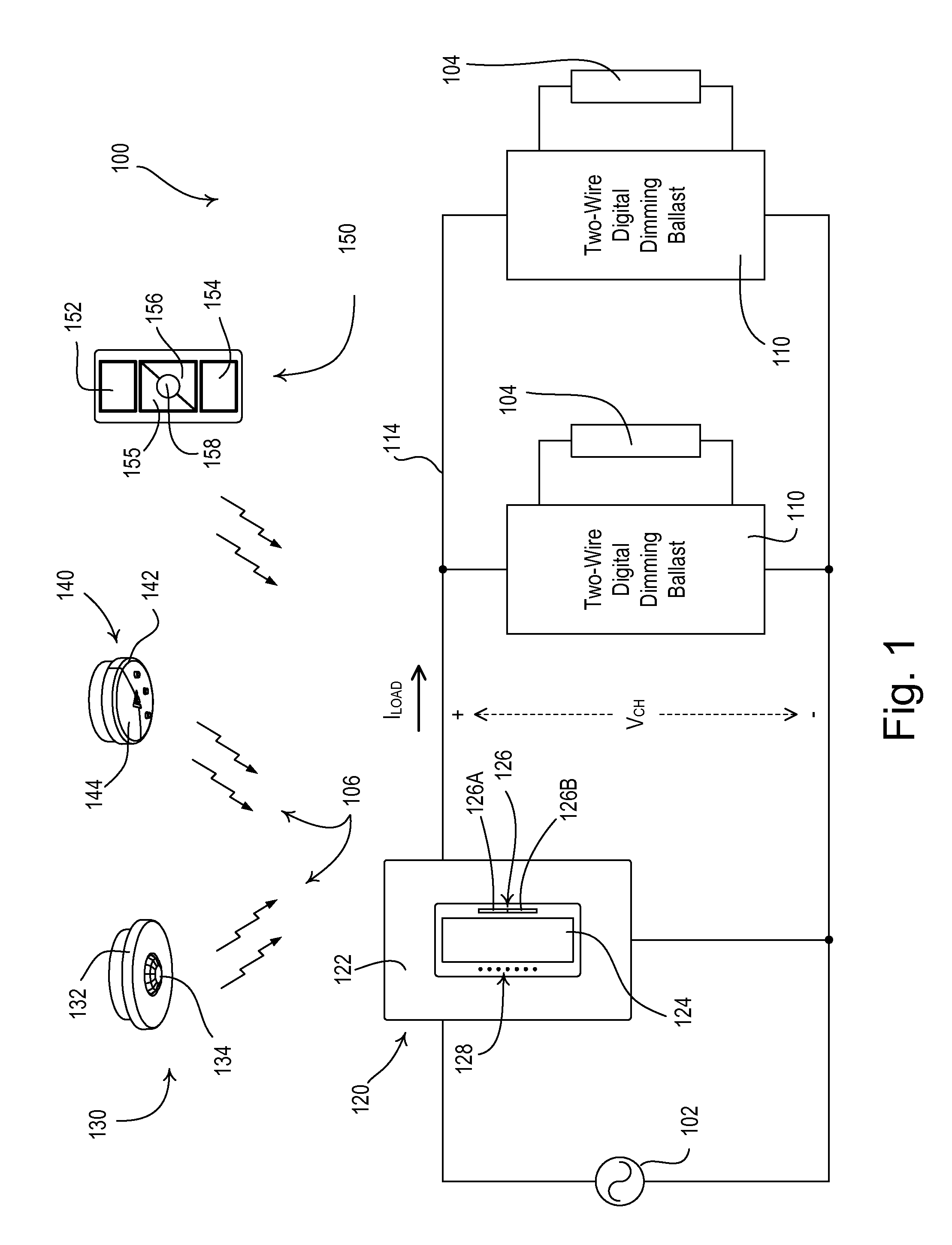
[0084]FIG. 1 is a simple wiring diagram of a load control system 100 having a plurality of two-wire load control devices, such as two-wire digital dimming ballasts 110, according to the present invention. The two-wire digital dimming ballasts 110 are coupled to respective lamps 104 for controlling the intensities of the lamps to a desired lighting intensity LDES between a low-end (i.e., minimum) intensity LLE (e.g., approximately 1%) and a high-end (i.e., maximum) intensity LHE (e.g., approximately 100%). The load control system 100 also comprises a digital ballast controller 120 (i.e., a remote control device) that is adapted to be coupled in series electrical connection between an alternating-current (AC) power source 102 and the two-wire digital dimming ballasts 110 via a circuit wiring 114. In other words, each digital dimming ballast 110 is coupled in series with the digital ballast controller 120 across the AC power source 102. As shown in FIG. 1, the digital ballast controlle...

second embodiment

[0140]FIG. 12 is a simplified flowchart of the timer interrupt procedure 700 that is executed by the microprocessor 214 of each digital ballast controller 120 to generate the reference and data edges of the transmitted digital messages according to the present invention. The microprocessor 214 executes the timer interrupt procedure 700 when the value of the timer equals the set interrupt time, for example, as set during the zero-crossing procedure 600. The microprocessor 214 first renders the controllably conductive device 210 conductive at step 712. If the variable m is equal to zero at step 714 (i.e., a reference edge was generated at step 712), the microprocessor 214 sets a base time t0 equal to the present value of the timer (i.e., the time at which the reference edge was generated) at step 716. The microprocessor 214 then prepares to generate a data edge in the next half-cycle by setting the variable m to one at step 718 and executing a data edge procedure 800, which will be de...

third embodiment

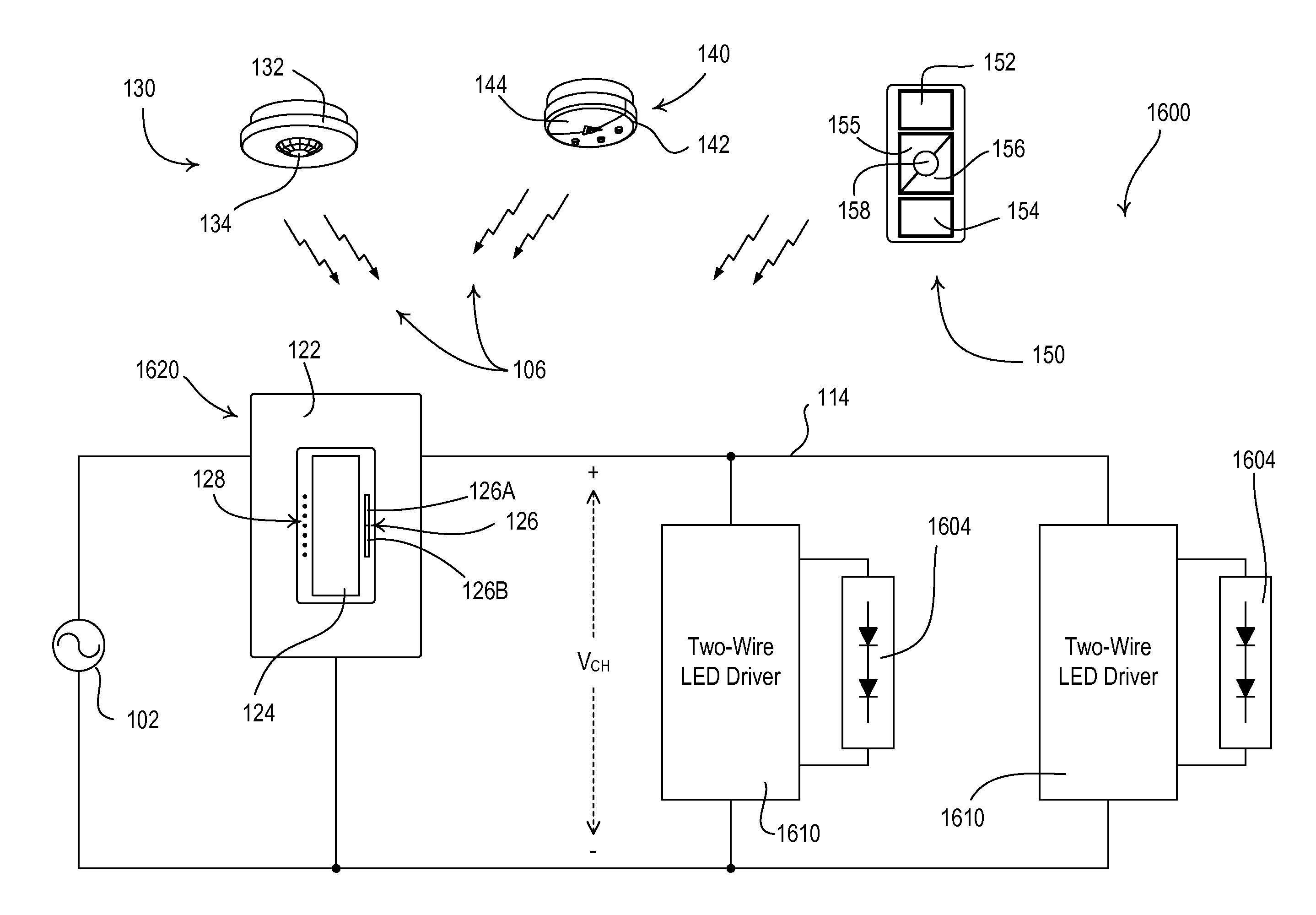
[0157]As previously mentioned, in some retrofit applications, the neutral wire coupled to the neutral side of the AC power source 102 may not be available in the wallbox of the digital ballast controllers 120. FIG. 20 is a simplified block diagram of a load control system 1300 comprising a two-wire remote control device, e.g., a two-wire digital ballast controller 1320, that is adapted to be coupled in series electrical connection between the AC power source 102 and the two-wire digital dimming ballasts 110 without a connection to the neutral side of the AC power source according to the present invention. The load control system 1300 further comprises an active load circuit 1390 that is coupled in parallel with the two-wire digital dimming ballasts 110 for providing a path for a charging current of a power supply 1420 (FIG. 21) of the digital ballast controller 1320 to be conducted as will be described in greater detail below. For example, the active load circuit 1390 may be housed ...


PUM


Abstract

A load control system comprises a load control device for controlling an electrical load receiving power from an AC power source, and a controller adapted to be coupled in series between the source and the load control device. The load control system may be installed without requiring any additional wires to be run, and is easily configured without the need for a computer or an advanced commissioning procedure. The load control device receives both power and communication over two wires, and the controller generates a phase-control voltage that has at least one timing edge in each half-cycle, and transmits digital messages by modulating a timing edge of the phase-control voltage relative to a reference edge. The controller may be operable to receive inputs from a plurality of different input devices, and the load control device may be operable to control a plurality of different loads.

Description

CROSS-REFERENCE TO RELATED APPLICATIONS[0001]This application is a non-provisional application of commonly-assigned U.S. Provisional Application No. 61 / 587,346, filed Jan. 17, 2012, entitled DIGITAL LOAD CONTROL SYSTEM PROVIDING POWER AND COMMUNICATION VIA EXISTING POWER WIRING, the entire disclosure of which is hereby incorporated by reference.BACKGROUND OF THE INVENTION[0002]1. Field of the Invention[0003]The present invention relates to a load control system for controlling the amount of power delivered to an electrical load, such as a lighting load. More particularly, the present invention relates to a “two-wire” load control system having load control devices that receive both power and communication over two wires from a digital controller that is easily configured without the need for a computer or an advanced commissioning procedure. In addition, the present invention relates to a two-wire load control system having a plurality of load control devices and a digital controlle...

Claims


Application Information

Patent Timeline
IPC IPC(8): H02J3/02H05B37/02H05B44/00
CPCH05B37/0263H05B37/0209H05B33/0845H05B37/0272H05B47/185H05B45/10H05B47/19Y02B20/40H05B47/115H05B47/11
Inventor TAIPALE, MARK S.STEINER, JAMES P.ZAHARCHUK, WALTER S.PESSINA, MICHAEL W.SPIRA, JOEL S.
Owner LUTRON TECH CO LLC
Why Eureka
Try Eureka