Stereoscopic imaging device and stereoscopic imaging method

a stereoscopic imaging and stereoscopic imaging technology, applied in the field of stereoscopic imaging devices and stereoscopic imaging methods, can solve the problems of reduced image quality, easy camera shake, and small camera shake, and achieve the effects of reducing the amount of parallax, and reducing the stereoscopic

Inactive Publication Date: 2013-07-18
FUJIFILM CORP
View PDF13 Cites 17 Cited by
  • Summary
  • Abstract
  • Description
  • Claims
  • Application Information

AI Technical Summary

Benefits of technology

[0032]The present invention allows to deepen a depth of focus and decrease the amount of parallax by further closing an aperture as the amount

Problems solved by technology

When the correction amount of camera shake exceeds a predetermined value, the imaging device determines that the 3D image is not suitable for a stereoscopic view and causes a 2D data creation unit to output photographed image data.
It is known that when a body to be an object is imaged onto an imaging surface of an imaging element by using an optical system such as a zooming lens, blurring

Method used


Image

  • Stereoscopic imaging device and stereoscopic imaging method
  • Stereoscopic imaging device and stereoscopic imaging method
  • Stereoscopic imaging device and stereoscopic imaging method

Examples


first embodiment

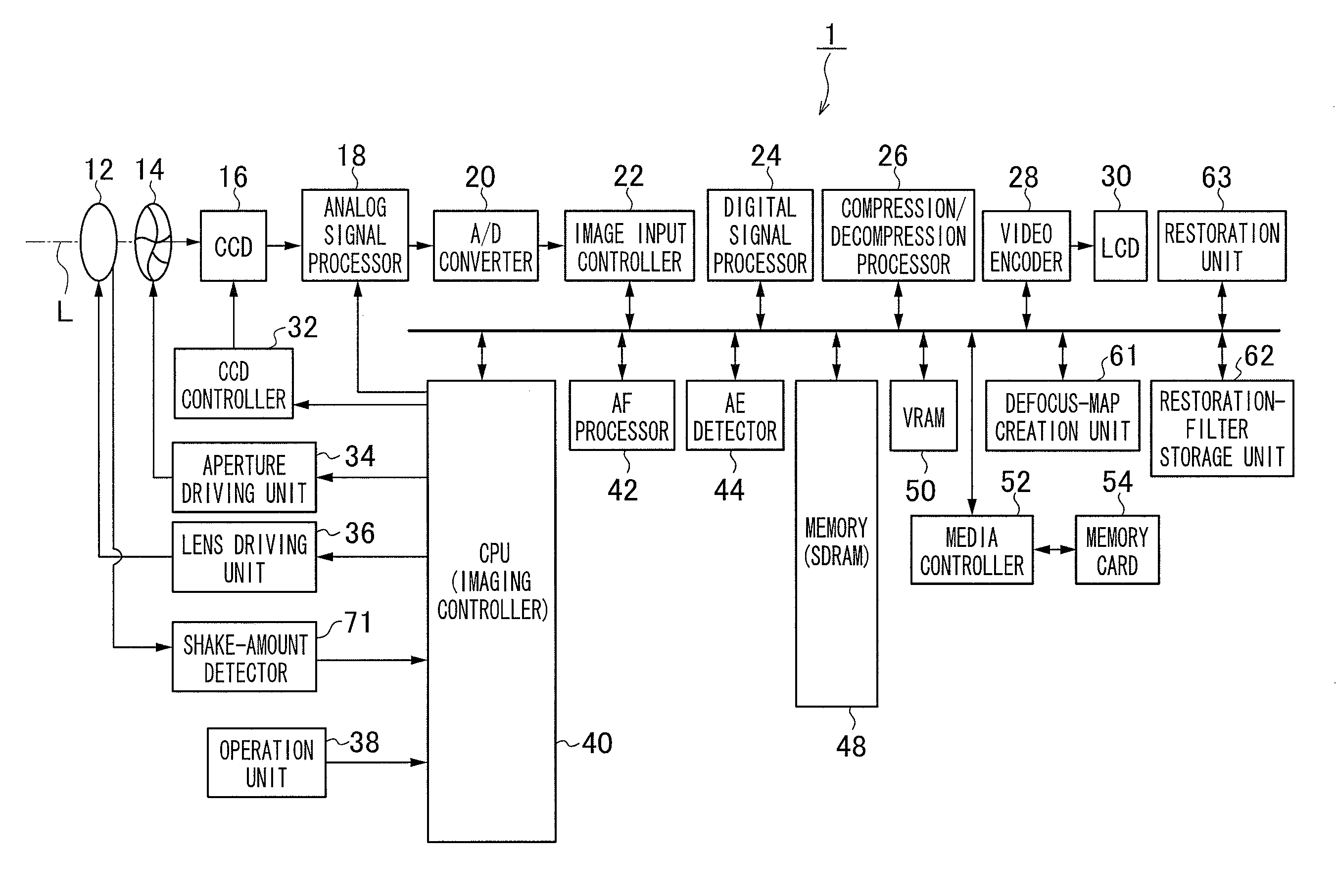
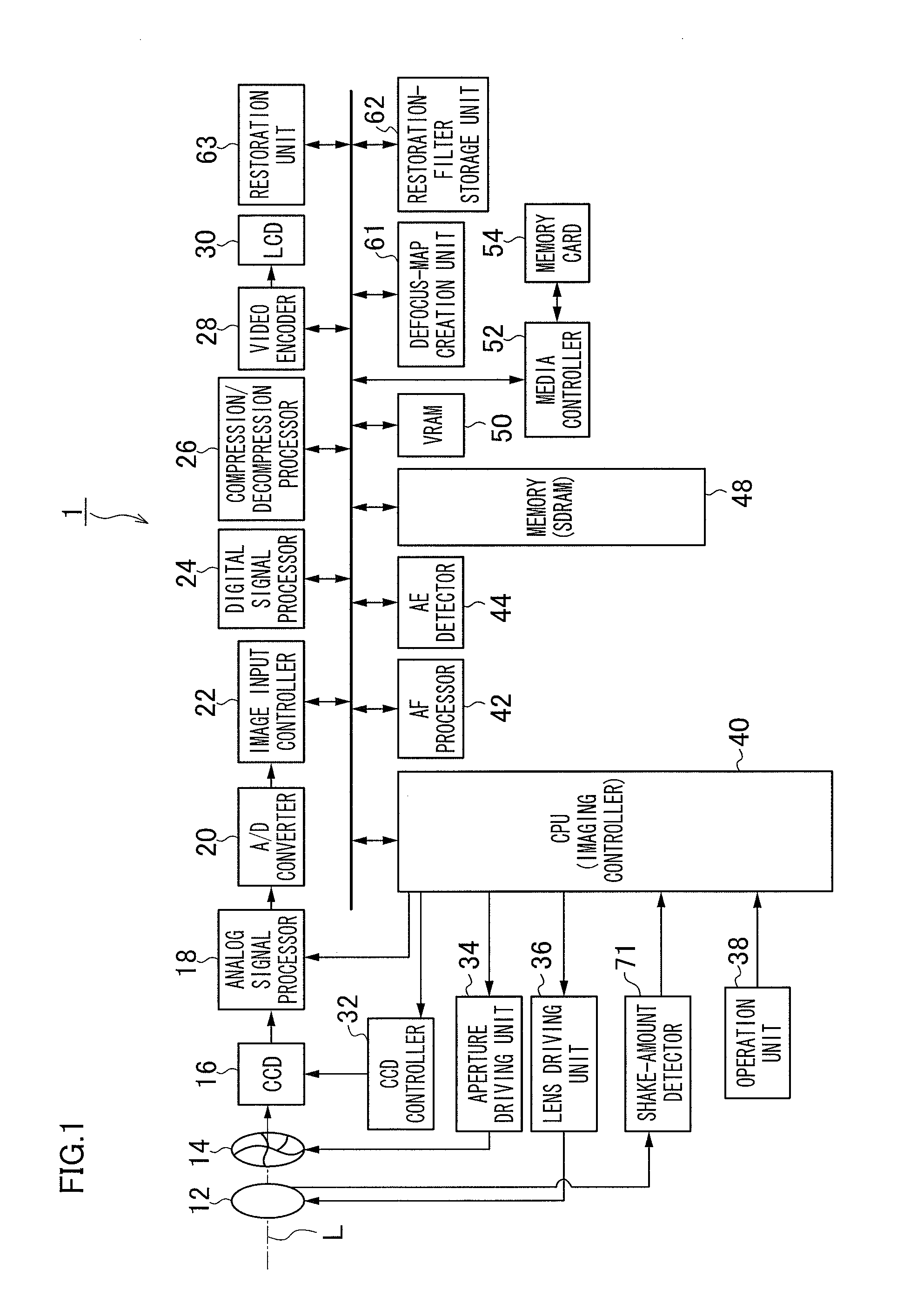
[0045]FIG. 1 is a block diagram showing an embodiment of a monocular stereoscopic imaging device in accordance with a first embodiment.

[0046]This monocular stereoscopic imaging device 1 records an imaged image in a memory card 54, and an overall operation of the device is managed and controlled by a central processing unit (CPU) 40.

[0047]The monocular stereoscopic imaging device 1 is provided with an operation unit 38 having, for example, a shutter button, a mode dial, a playback button, a MENU / OK key, a cross key, and a BACK key. Signals from the operation unit 38 are input to the CPU 40. The CPU 40 controls circuits in the stereoscopic imaging device 1 on the basis of the input signals to perform, for example, lens driving control, aperture driving control, photograph operation control, image processing control, recording / playback control of image data, and display control of a stereoscopic liquid crystal monitor 30.

[0048]The shutter button is an operation button for inputting the...

second embodiment

[0090]FIG. 7 is a block diagram of a monocular stereoscopic imaging device 2 in accordance with a second embodiment. The same elements as the first embodiment shown in FIG. 1 will be denoted by the same reference numerals, and detailed description thereof will be omitted.

[0091]This monocular stereoscopic imaging device 2 further includes a shake-amount-range determination and control unit 72 and a shake correction unit 73. The shake correction unit 73 optically corrects a shake of an object image corresponding to the amount of shake in a yaw direction and a pitch direction detected by the shake-amount detector 71, according to the control of the shake-amount-range determination and control unit 72. For example, the shake correction unit 73 controls a yaw-direction actuator and a pitch-direction actuator to move the lens 12 in the direction negating the detected amount of shake, thereby preventing an image shake (lens-shift method). As a method of the optical shake correction for use...

third embodiment

[0099]FIG. 9 is a block diagram of a monocular stereoscopic imaging device 3 in accordance with a third embodiment. The same elements as the first embodiment and the second embodiment shown in FIG. 1 will be denoted by the same reference numerals, and detailed description thereof will be omitted.

[0100]The monocular stereoscopic imaging device 3 further includes a shake-direction detector 74 and a shake-direction determination and control unit 75. The shake-direction detector 74 detects a direction in which a shake occurs (a yaw direction and / or a pitch direction).

[0101]FIG. 10 is a flowchart of imaging processing performed by the monocular stereoscopic imaging device 2.

[0102]S21 is the same as the S1.

[0103]In S22, the shake-direction detector 74 detects, as a shake direction, the direction corresponding to the larger one of the amount of shake in the yaw direction and the amount of shake in the pitch direction detected by the shake-amount detector 71. If the amount of shakes in both...


PUM


Abstract

A stereoscopic imaging device, wherein the aperture controller performs a second aperture control in which the larger the amount of shake detected by the shake detector becomes, the further the amount of opening of the aperture unit decreases than the amount of opening required for the first aperture control. The present invention allows to deepen a depth of focus and decrease the amount of parallax by further closing an aperture as the amount of shake becomes larger, so that a stereoscopic effect is weakened when the amount of shake is large, thereby reducing an influence on viewers.

Description

CROSS-REFERENCE TO RELATED APPLICATIONS[0001]This application is a continuation application and claims the priority benefit under 35 U.S.C. §120 of PCT Application No. PCT / JP2011 / 063880 filed on Jun. 17, 2011 which application designates the U.S., and also claims the priority benefit under 35 U.S.C. §119 of Japanese Patent Application No. 2010-203394 filed on Sep. 10, 2010, which applications are all hereby incorporated by reference in their entireties.TECHNICAL FIELD[0002]The present invention relates to a stereoscopic imaging device and a stereoscopic imaging method, and more particularly, to a technique in which object images having passed through different regions in two directions of a photographing lens are imaged onto imaging elements to obtain different viewpoint images.BACKGROUND ART[0003]Conventionally, an imaging device having an optical system shown in FIG. 11 is known as a monocular stereoscopic imaging device (Patent Literature 1).[0004]This optical system has a config...

Claims


Application Information

Patent Timeline
IPC IPC(8): H04N13/02
CPCH04N5/23258H04N5/2328H04N13/0217H04N5/23212H04N2209/045H04N13/0203H04N13/0022H04N13/0257H04N13/128H04N13/218H04N13/257H04N23/672H04N23/673H04N23/685H04N23/6812H04N13/204
Inventor HAYASHI, KENKICHI
Owner FUJIFILM CORP
Why Eureka
Try Eureka