Power transmission device

a transmission device and power technology, applied in the direction of friction gearings, gearing elements, gearing rings, etc., can solve the problems of compact equipment, increased installation height, and difficulty in applying the power transmission device b>

Active Publication Date: 2013-07-25
SEJIN IGB
View PDF6 Cites 17 Cited by
  • Summary
  • Abstract
  • Description
  • Claims
  • Application Information

AI Technical Summary

Benefits of technology

[0007]The present invention provides a power transmission device having a simple structure which may reduce installation height so as to be easily applied to compact equipment, may reduce use of complicated peripheral accessories unlike a conventional technology, and further, may remarkably reduce frequencies of a maintenance work and a cleaning work compared to the conventional technology, thereby preventing a process delay.

Problems solved by technology

However, since the power transmission device 1 of FIG. 1 has a structure in which the shaft 7 protrudes outwardly and the pinion 6 is coupled to the end portion of the shaft 7, foot print, in particular, installation height H, increases so that it is difficult to apply the power transmission device 1 of FIG. 1 to compact equipment.
Also, there are various problems such that complicated peripheral accessories such as a gear box or a shrink fitting to coupling are needed, the vicinity of equipment is contaminated because lubrication oil is coated on an outer surface of the pinion 6, and the maintenance work and the cleaning work are frequently needed due to its structure so that the process is delayed.

Method used


Image

  • Power transmission device
  • Power transmission device
  • Power transmission device

Examples


Embodiment Construction

Technical Problem

[0007]The present invention provides a power transmission device having a simple structure which may reduce installation height so as to be easily applied to compact equipment, may reduce use of complicated peripheral accessories unlike a conventional technology, and further, may remarkably reduce frequencies of a maintenance work and a cleaning work compared to the conventional technology, thereby preventing a process delay.

DESCRIPTION OF THE DRAWINGS

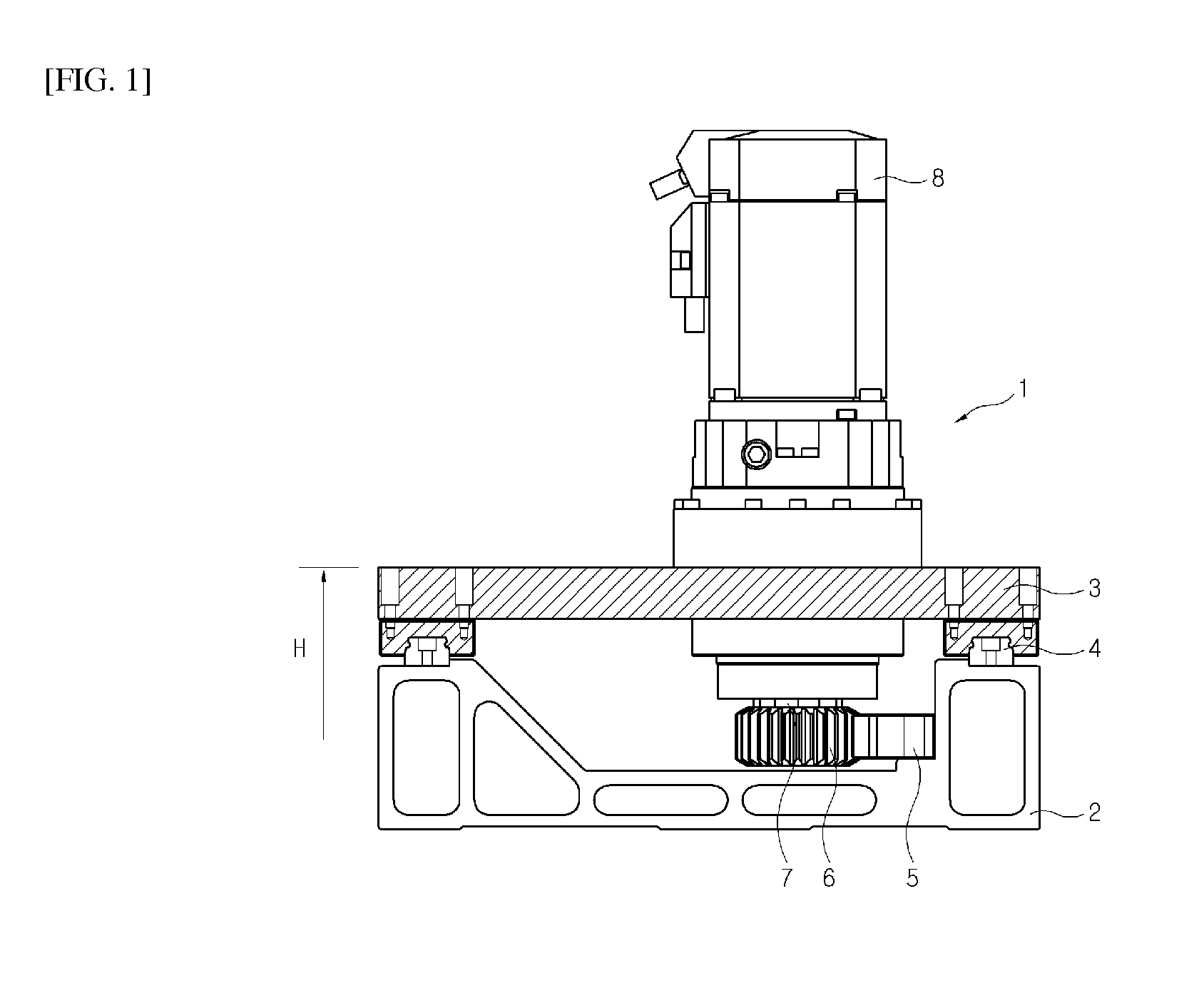
[0008]FIG. 1 is a side structural view schematically illustrating a use state of a conventional power transmission device 1.

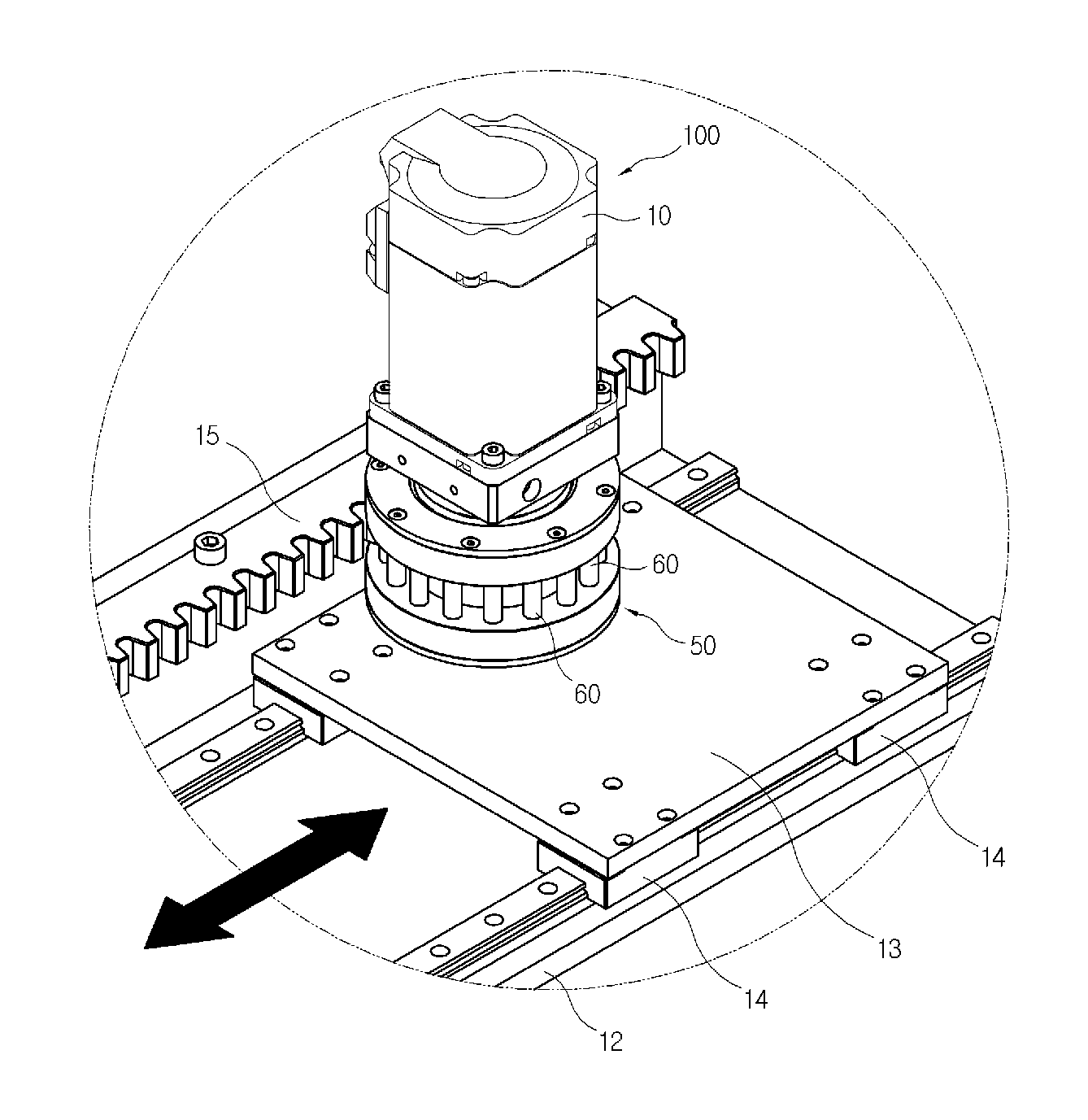
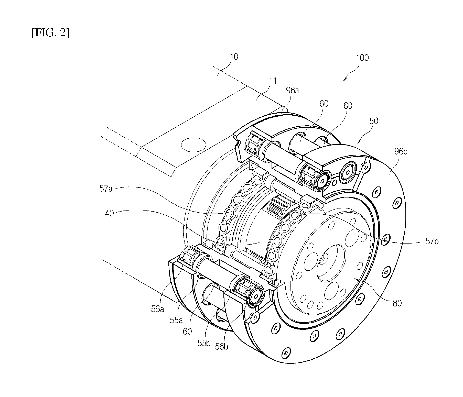
[0009]FIG. 2 is a partially cut-away perspective view schematically illustrating a power transmission device according to an embodiment of the present invention.

[0010]FIG. 3 is a perspective view schematically illustrating a separated state of a motor adaptor of FIG. 2.

[0011]FIG. 4 is an exploded perspective view of FIG. 2.

[0012]FIG. 5 is a magnified view of an area A of FIG. 4.

[0013]FIG. 6 is a p...


PUM


Abstract

Disclosed is a power transmission device. A power transmission device according to one embodiment of the present invention includes: an input gear connected to a motor so that the input gear may rotate by the motor in a forward and backward direction; a planetary gear train circumscribing the input gear with respect to the input gear and rotating in association with the rotation of the input gear; a ring gear inscribing the planetary gear train and rotating relative to the planetary gear train; a main frame having a plurality of rollers coupled along the circumferential direction and interacting with a rack, and coupled with the ring gear on the outside of the ring gear; an irrotational rear side fixture disposed on an area where the input gear is positioned; and an irrotational front side fixture disposed at the opposite side of the irrotational rear side fixture via the ring gear and the main frame therebetween and coupled with the irrotational rear side fixture.

Description

TECHNICAL FIELD[0001]The present invention relates to a power transmission device, and more particularly, to a power transmission device having a simple structure which may reduce installation height so as to be easily applied to compact equipment, may reduce use of complicated peripheral accessories unlike a conventional technology, and further, may remarkably reduce frequencies of a maintenance work and a cleaning work compared to the conventional technology, thereby preventing a process delay.BACKGROUND ART[0002]A power transmission device is generally classified into a rack and pinion for converting a rotational motion into a linear motion or vice versa and a gear train for converting a rotation speed and torque while transferring only a rotational motion. Typically, a power transmission system of a power transmission device mainly uses a tooth shape based on an involute curve, but a tooth shape based on a cycloid curve and a pin gear are uncommonly used. The power transmission ...

Claims


Application Information

Patent Timeline
Patent Type & Authority Applications(United States)
IPC IPC(8): F16H19/04
CPCF16H1/28Y10T74/18104F16H55/10F16H19/04F16H57/0482F16H57/08
Inventor LIM, SUN HO
Owner SEJIN IGB
Why Eureka
Try Eureka