
Tube support structure for aircraft

a tube support and aircraft technology, applied in the direction of machine supports, other domestic articles, transportation and packaging, etc., can solve the problems of increased cost of producing the bracket b>104/b>, inability to continuously adjust the angle of the tube b>103/b>, and failure to meet the requirements of the application. to achieve the effect of suppressing the occurrence of preload

Active Publication Date: 2013-07-25
MITSUBISHI HEAVY IND LTD
View PDF12 Cites 25 Cited by
  • Summary
  • Abstract
  • Description
  • Claims
  • Application Information

AI Technical Summary

Benefits of technology

The present invention provides a tube support structure for aircraft that can suppress a preload. This is achieved by using an eccentric sleeve that allows the tube to be adjusted in the Z direction by rotating. The structure also includes a second member that supports the first curved surface slidably using a second curved surface. This allows for continuous adjustment of the tube angle and prevents preload. Overall, this invention allows for better control and positioning of the tube and reduces the likelihood of damage during operation.

Problems solved by technology

Thus, a cost for producing the bracket 104 is increased.
Thus, attachment mistakes may occur.
In addition, the angle of the tube 103 cannot be adjusted continuously.

Method used


Image

  • Tube support structure for aircraft
  • Tube support structure for aircraft
  • Tube support structure for aircraft

Examples


first embodiment

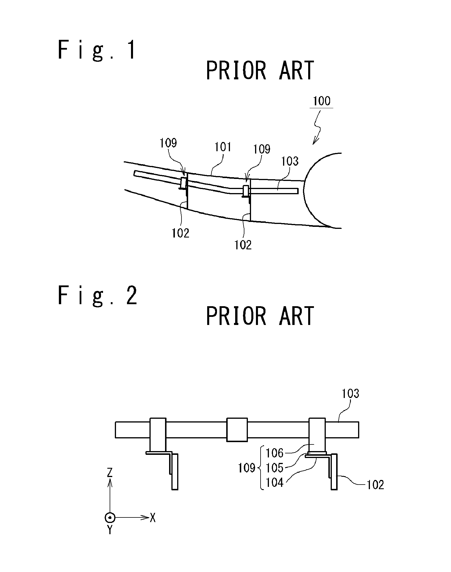
[0047]A tube support structure according to the present embodiment is used to support a tube arranged inside a main wing in an aircraft, as shown in FIG. 1. The main wing in the aircraft is assumed to be made of CFRP (Carbon Fiber Reinforced Plastic).

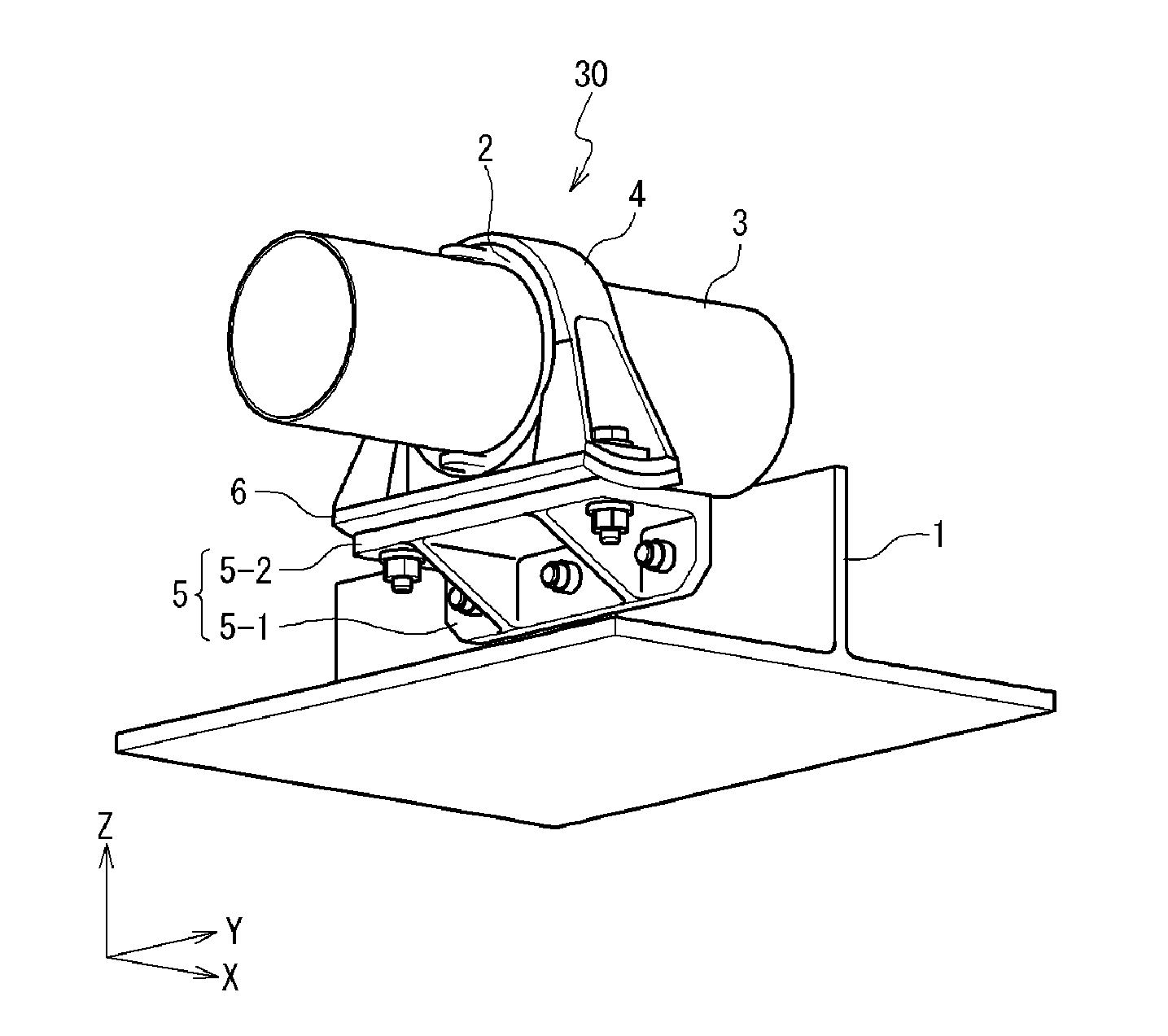
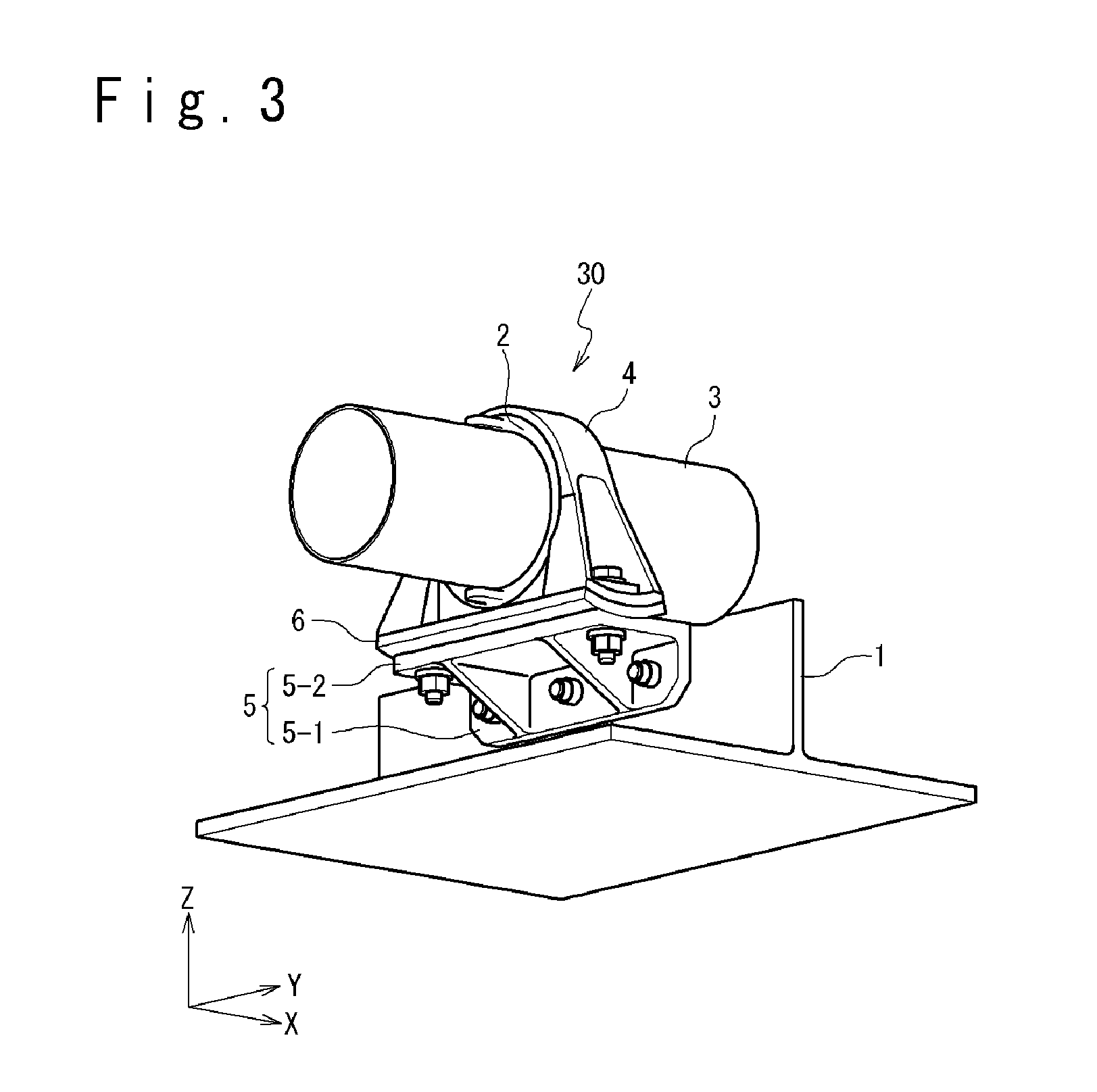
[0048]FIG. 3 is a perspective view showing a tube support structure 30 according to the present embodiment. In FIG. 3, an X direction, a Y direction and a Z direction which are orthogonal to one another are defined. This tube support structure 30 is attached to a structure body 1.

[0049]The structure body 1 is fixed to an airframe, has a shape of a flat plate and is arranged in parallel to an XZ plane. The tube support structure 30 supports a tube 3 extending along the X direction, above the structure body 1 (the Z direction side).

[0050]FIG. 4 is a cross-sectional view showing an YZ section of the tube support structure 30. FIG. 5 is the view when the tube support structure 30 is viewed from the Y direction side. FIG. 6 is the exploded p...

second embodiment

[0073]Next, a second embodiment will be described.

[0074]FIG. 11 is a perspective view showing a tube support structure 30 according to the present embodiment. FIG. 12 is a cross-sectional view of the tube support structure 30 in the YZ plane. FIG. 13 is a cross-sectional view of the tube support structure 30 on the XZ plane. FIG. 14 is an exploded perspective view showing the tube support structure 30.

[0075]As shown in FIG. 14, in the present embodiment, a spherical sleeve (first member) 19 (19-1, 19-2) is provided on the inner side of the eccentric sleeve 2 (second member). The tube 3 penetrates through the spherical sleeve 19 and is supported by the spherical sleeve 19. Also, an eccentric sleeve support member 20 is used instead of the saddle 6 and the bracket 5. Since the other configurations can be made similar to the first embodiment, their detailed explanations are omitted.

[0076]The eccentric sleeve support member 20 is such that the saddle 6 and the bracket 5 in the first emb...


PUM


Abstract

A tube support structure for an aircraft includes: a parallel movement mechanism configured to support the tube movably in parallel; and an angle adjustment mechanism configured to support the tube angle-adjustably. The parallel movement mechanism includes: an eccentric sleeve, through which the tube passes, configured to adjust a position of the tube in a Z direction perpendicular to the X direction, and a Y direction adjustment mechanism configured to adjust a position of the eccentric sleeve in a Y direction perpendicular to the X direction and the Z direction. The angle adjustment mechanism includes: a first member configured to have a first curved surface and support the tube, and a second member configured to have a second curved surface with a shape corresponding to the first curved surface, have contact slidably with the first curved surface at the second curved surface, and support the first member by the second curved surface. Each of the first curved surface and the second curved surface is formed such that a cross-sectional shape in an XZ plane is a circular arc shape, and an angle of the tube is adjusted by sliding the first curved surface with respect to the second curved surface. Thus, a tube support structure for aircraft, which can suppress a preload, is provided.

Description

TECHNICAL FIELD[0001]The present invention relates to a tube support structure for an aircraft.BACKGROUND ART[0002]Many tubes, such as a fuel supplying tube and the like, are arranged inside an aircraft. In order to support the foregoing tubes, a tube support structure is provided inside the aircraft.[0003]For the tube support structure, a preload applied to a tube is required to be suppressed. Moreover, there is a case that the aircraft is deflected by lifting power and the like received during its flight. In particular, a main wing portion is easily bent by a load such as lifting power generated during operations. With the deflection in an airframe, the tube receives a load at a portion of the tube support structure. When the preload exists in the tube, in addition to the load caused by the deflection in the airframe, a load corresponding to the preload is applied to the tube. Moreover, the aircraft repeats its takeoff and landing. This implies that the load caused by the deflecti...

Claims


Application Information

Patent Timeline
Patent Type & Authority Applications(United States)
IPC IPC(8): F16L3/12
CPCF16L3/1222B64D37/005F16L3/1091F16L3/16F16L5/10F16L5/025Y02T50/40F16L3/1016F16L3/1008F16L3/10F16M11/10
Inventor MINAMI, KEISUKE
Owner MITSUBISHI HEAVY IND LTD
Learn More