Flicker-Free LED Driver Circuit with High Power Factor

a led driver circuit and power factor technology, applied in the field of ac led driver circuits, can solve the problems of reducing the power factor of the conventional led driver circuit, the difficulty of using the conventional ac outlet, and the distortion of the photos, so as to solve the flickering problem

Inactive Publication Date: 2013-07-25
LUXUL TECH
View PDF4 Cites 10 Cited by
  • Summary
  • Abstract
  • Description
  • Claims
  • Application Information

AI Technical Summary

Benefits of technology

[0020]Therefore, the invention can effectively solve the flickering probl

Problems solved by technology

However, the LED is conductive only in a single direction and thus therefore difficult to be used on the conventional AC outlet.
The net result is that the images

Method used


Image

  • Flicker-Free LED Driver Circuit with High Power Factor
  • Flicker-Free LED Driver Circuit with High Power Factor
  • Flicker-Free LED Driver Circuit with High Power Factor

Examples


Embodiment Construction

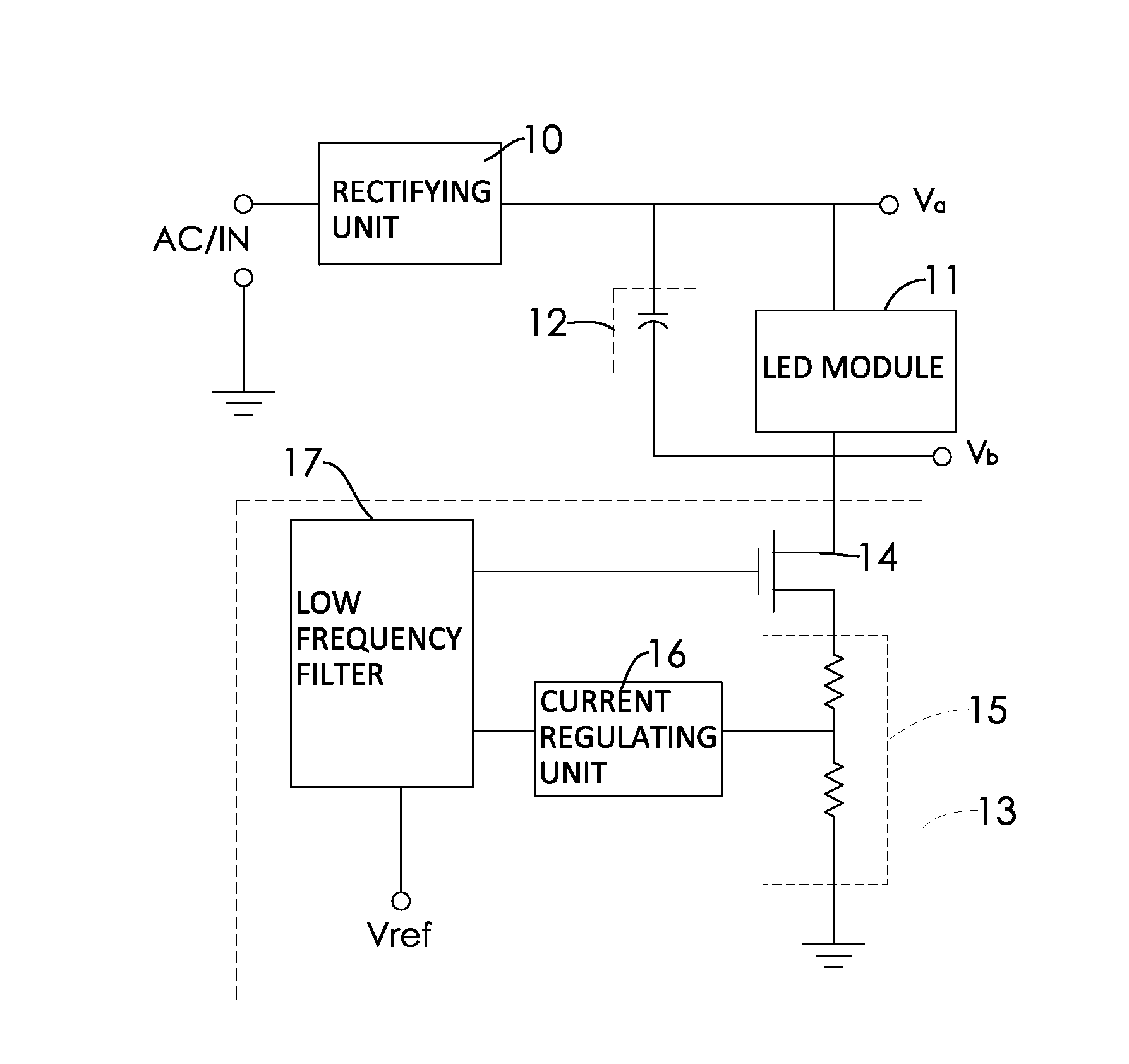
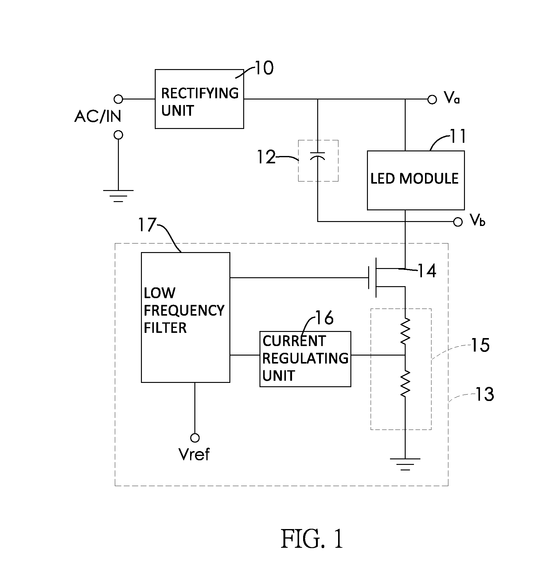
[0032]FIG. 1 shows the flicker-free LED driver circuit with a high power factor. The circuit comprises a rectifying unit 10, an LED module 11, a capacitor module 12, and a constant current circuit 13.

[0033]The input terminal of the rectifying unit 10 connects to an AC power supply AC / IN, and converts the AC power supply AC / IN into a pulsed DC power supply, which is then output by the output terminal thereof. The rectifying unit 10 can be a full-wave rectifying circuit or a half-wave rectifying circuit. In this embodiment, it is a full-wave rectifying circuit.

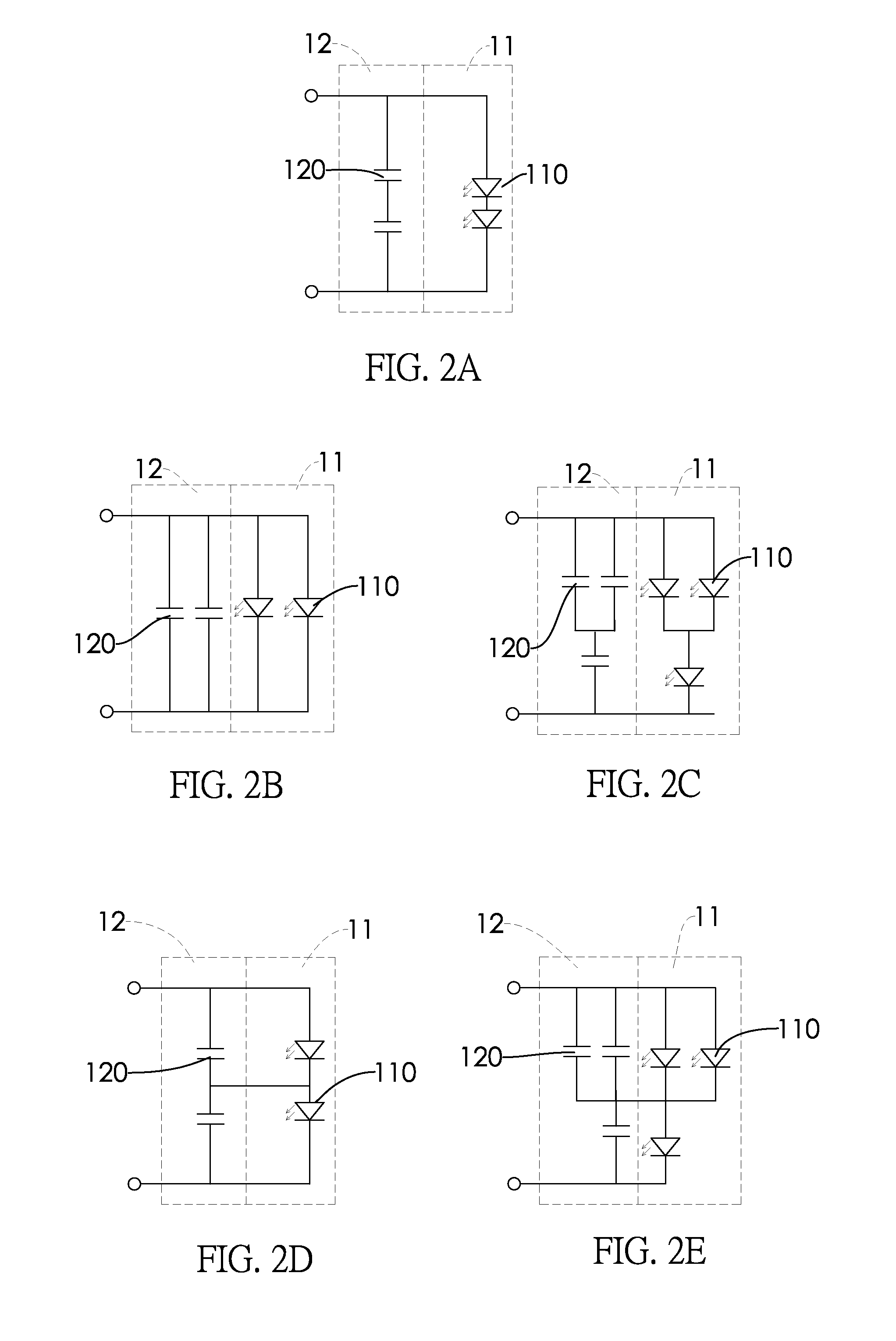
[0034]The LED module 11, as shown in FIGS. 2A to 2C, includes a plurality of LED light sources 110, and electrically connects to the output terminal of the rectifying unit to constitute a power loop. In this embodiment, the LED light sources are connected in parallel, in series, or in both series and parallel before connecting to the output terminal of the rectifying unit 10 to constitute a power loop. In this case, the pulsed D...


PUM


Abstract

A flicker-free LED driver circuit with a high power factor has a rectifying unit connected with an AC power source, an LED module connected in series with the rectifying unit, a capacitor module connected in parallel with the LED module, and a constant current circuit connected in series with the LED module and the capacitor module. When the voltage output by the rectifying unit is smaller than a junction voltage of the LED module, the capacitor module discharges to the LED module so that the LED module does not go out, thereby eliminating the flickering. The input impedance of the rectifying unit can be regarded as a capacitive reactance element connected in parallel with a nonlinear resistive element. The internal resistance of the constant current source approaches infinity. Therefore, the power factor of the flicker-free LED driver circuit approximates 1, achieving a high power factor.

Description

CROSS-REFERENCE TO RELATED APPLICATIONS[0001]This application claims the benefit of Taiwan patent application No. 101102578, filed on Jan. 20, 2012, the disclosure of which is incorporated herein in its entirety by reference.BACKGROUND OF THE INVENTION[0002]1. Field of the Invention[0003]The invention relates to an AC LED driver circuit and, in particular, to a flicker-free LED driver circuit with a high power factor.[0004]2. Description of Related Art[0005]The light-emitting diode (LED) is one of the most common lighting appliances currently available on the market. In comparison with the traditional incandescent light bulbs, LED has higher luminous efficiency and power-saving features. However, the LED is conductive only in a single direction and thus therefore difficult to be used on the conventional AC outlet. For this, the industry has developed an AC LED driver circuit. As shown in FIG. 6, the conventional AC LED driver circuit contains: a rectifying unit 20, an LED module 21,...

Claims


Application Information

Patent Timeline
IPC IPC(8): H05B33/08H05B44/00
CPCH05B33/0842Y02B20/345H05B33/0812H05B45/395Y02B20/30H05B45/355
Inventor PAN, CHENG-HUNGYUH, PERNG-FEI
Owner LUXUL TECH
Why Eureka
Try Eureka